Solids separation system

a solid separation and system technology, applied in the direction of cleaning process and equipment, chemistry apparatus and processes, cleaning liquids, etc., can solve the problems of reducing the separation retention time, affecting the separation efficiency, and increasing the wear of equipmen

Active Publication Date: 2006-06-22
ECOSERV TECH
View PDF2 Cites 6 Cited by
  • Summary
  • Abstract
  • Description
  • Claims
  • Application Information

AI Technical Summary

Benefits of technology

[0007] It is another object of the present invention to provide a solid separation system that can separate the solids based on a “batch” method, allowing the operator to schedule maintenance of the vessel at a predetermined time.

Problems solved by technology

The sand and silt accumulate in the separation equipment creating numerous problems to the equipment owners, including reduction in the separation retention time by displacing gas or volume, blocking free passage of fluids thereby affecting the separation efficiency and carrying over sand to other valves and equipment, thereby increasing wear of the equipment through abrasion and the like.
The conventional process exposes the workers to potentially dangerous conditions including exposure to Benzine, a known carcinogen, and to oxygen deficient atmosphere.
Additionally, the explosive environment of the hydrocarbon separation causes the threat of combustion by a simple static spark.
Even further, the cost of shutting the well production can reduce the profit of the well owner by millions of dollars a day.
That technology, while offering great advances over conventional then-current technology has certain disadvantages as it allows removal of approximately 65% of the solids.

Method used


Image

  • Solids separation system
  • Solids separation system
  • Solids separation system

Examples


Embodiment Construction

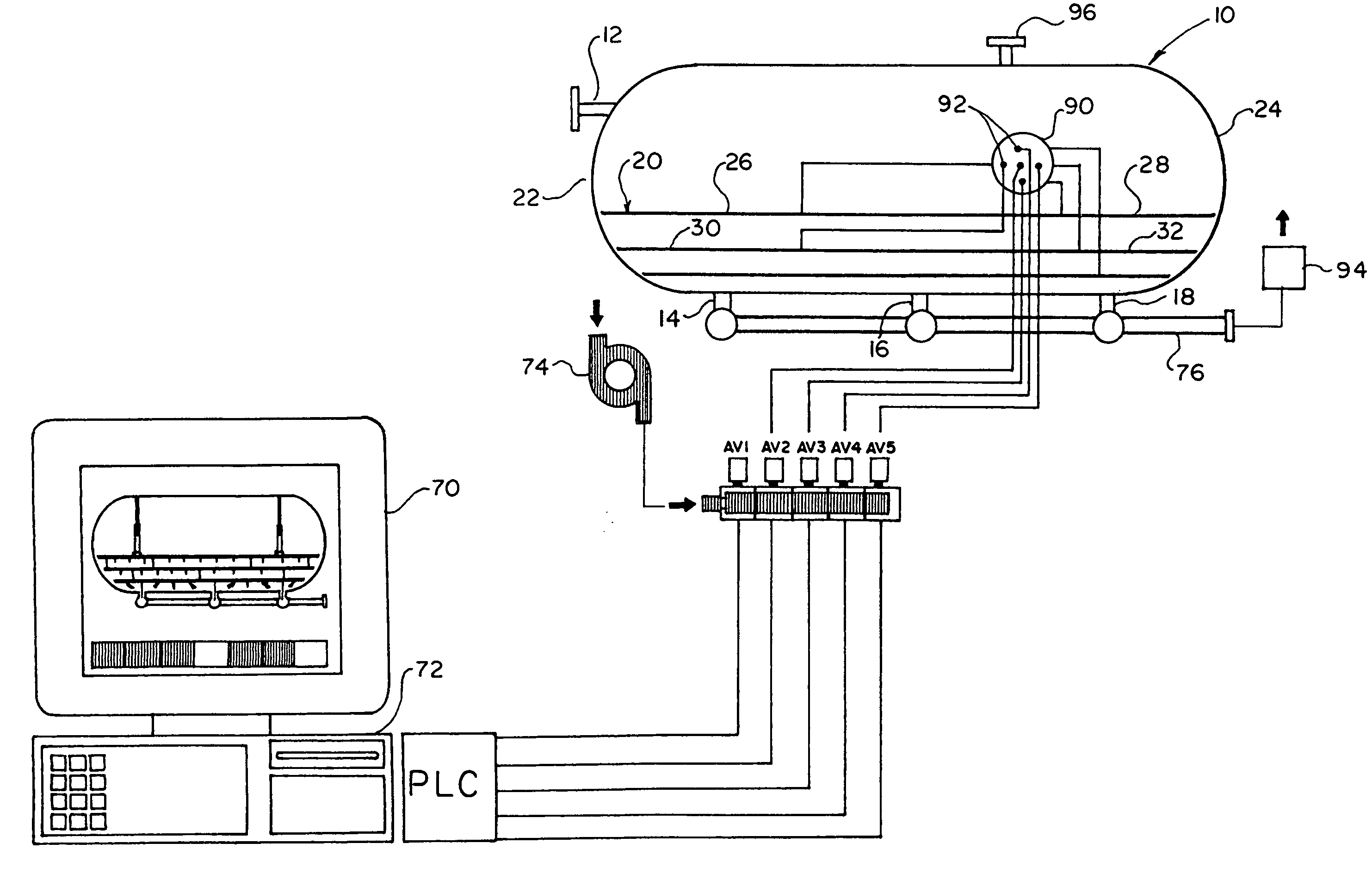
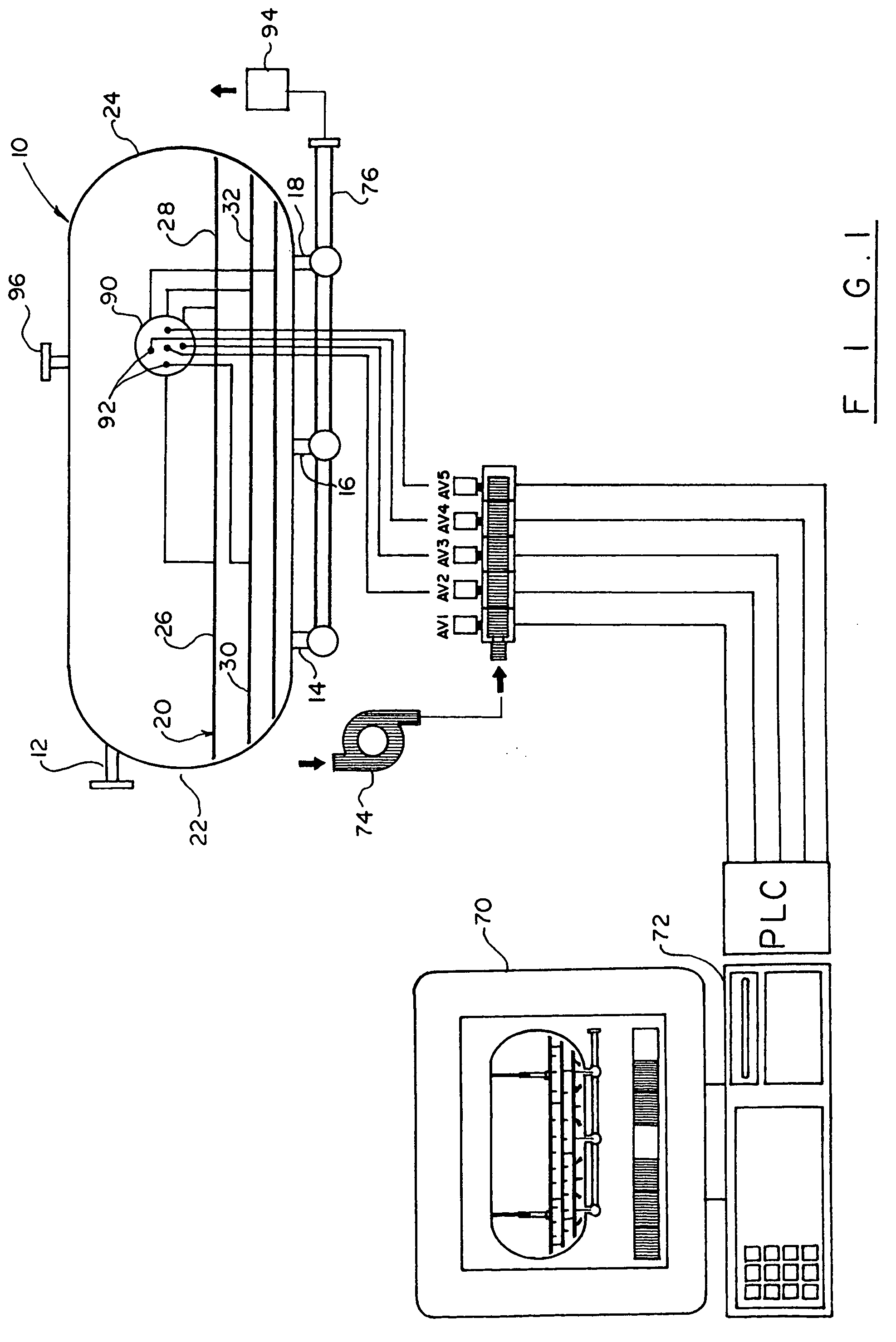
[0020] Turning now to the drawings in more detail, numeral 10 designates a vessel, tank or other container, wherein the well water containing solid particles and perhaps some hydrocarbons is delivered. The vessel 10 has in inlet 12 located at the top of the vessel and a plurality of outlets 14, 16 and 18 located in the bottom of the vessel. The vessel 10 may also have a separate outlet (not shown) for hydrocarbons, if present, and clean water.

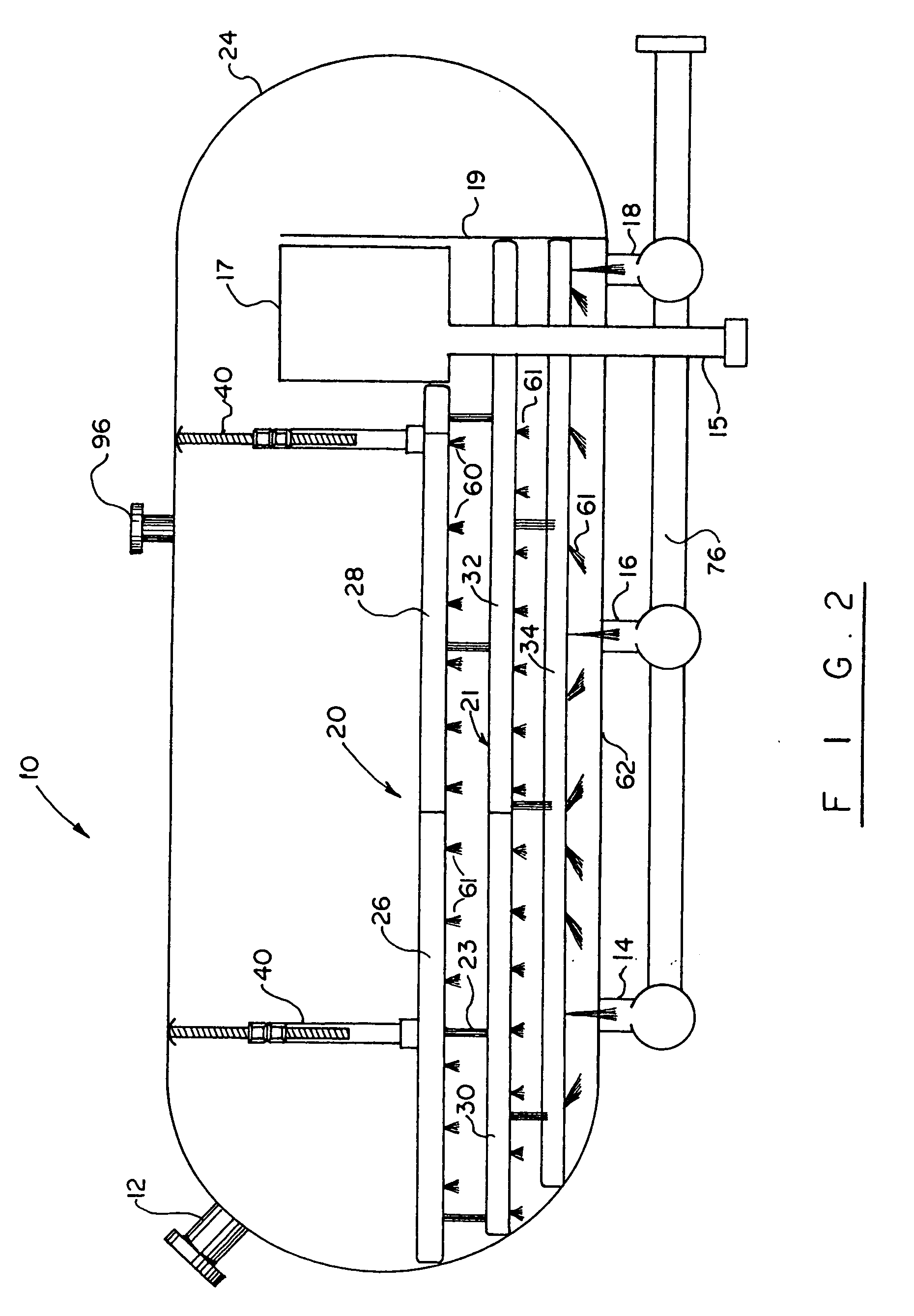
[0021] Mounted within the vessel 10 is a manifold assembly comprised of a plurality of hollow manifolds, or conduits, arranged in the lower part of the vessel 10. The manifolds extend along substantially entire length of the vessel 10 in a generally horizontal orientation. Portions of the manifold assembly are positioned in a vertically spaced relationship to each other.

[0022] An upper manifold 20 is oriented substantially horizontally in the vessel 10 and extends from a first end 22, to the second end 24 of the vessel 10. The upper manifold ...


PUM

PropertyMeasurementUnit
timeaaaaaaaaaa
volumeaaaaaaaaaa
lengthaaaaaaaaaa

Abstract

A solids removal system for use in removing sand and silt from well production fluids. The system has a manifold assembly provided with jetting nozzles, which is installed in a liquid- and solids-containing vessel, where solids have settled in the walls. The jetting nozzles deliver, in a pre-determined sequence, a solids-dislodging fluid, causing the solids to become suspended in the fluid. The dislodged solids and fluid are then extracted by pump from the vessel and directed to a solid-fluid separator. Solids-free fluid is returned for re-re-circulation through the vessel, while the solids are moved to a containment location.

Description

BACKGROUND OF THE INVENTION [0001] The present invention relates to a system of solids separation, and more particularly to a system for separating sand and silt from well bore water used in the oil and gas industry. [0002] Presently, there exist an estimated 5000 oil and gas production facilities in the U.S. Gulf of Mexico alone. All of these facilities employ one type or another of solids separation equipment. Such equipment is necessary to separate each fraction of the produced fuel and gases so that they may be directed in a clean state to their particular means of storage, transportation and ultimate sale. For wells, which produce sand and solids, the separation equipment acts as a collection mechanism for the solids. During drilling or production operation, particles of sand and silt are brought to the surface with the oil gas and produced water. The sand and silt accumulate in the separation equipment creating numerous problems to the equipment owners, including reduction in ...

Claims


Application Information

Patent Timeline
Patent Type & Authority Applications(United States)
IPC IPC(8): B08B7/04B08B9/093B08B3/04
CPCB08B9/0933
Inventor DESORMEAUX, KENNY
Owner ECOSERV TECH
Why Eureka
Try Eureka