Cemented carbide inserts for earth-boring bits
a technology of cement carbide and inserts, which is applied in the direction of drill bits, earth-moving mining, drilling accessories, etc., can solve the problems of inability to insert, and inability to meet the requirements of drilling
- Summary
- Abstract
- Description
- Claims
- Application Information
AI Technical Summary
Benefits of technology
Problems solved by technology
Method used
Image
Examples
example 1
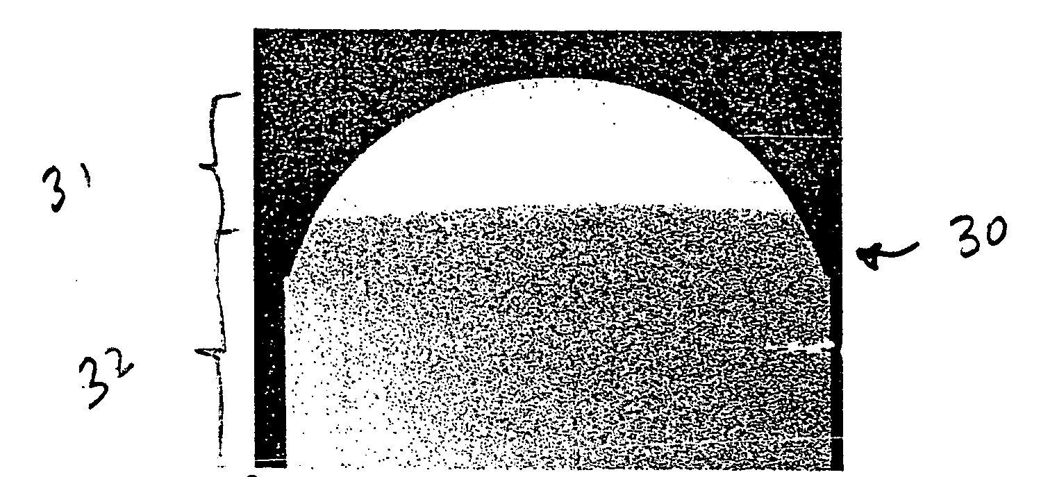
[0050]FIG. 3(a) shows an embodiment of a cutting insert 30 of the present invention having a cutting zone 31 comprising a cemented carbide grade having a Co content of 10 weigh percent and an average WC grain size of 0.8μm. The cutting zone 31 has a hardness of 92.0 HRA. The second zone, the body zone 32, comprises a cemented carbide grade having a Co content of 10 weigh percent and an average WC grain size of 3.0 μm. The body zone 32 has a hardness of 89.0 HRA. FIGS. 3(b)-3(d) illustrate the microstructures of the cutting zone (FIG. 3(b)), the transition zone between the cutting zone 31 and the body zone 32 (FIG. 3(c)), and the body zone 32(Figure 3(d)), respectively. FIG. 3(e) illustrates the exterior of the insert.
[0051] The insert of example 1 was fabricated by filling a portion of the dome of the lower punch with the first cemented carbide powder corresponding to the cutting zone, followed by raising the die table and filling the mold with powder grade corresponding to the bod...
example 2
[0052]FIG. 4(a) shows an embodiment of a cutting insert 41 of the present invention having a cutting zone 41 comprising a cemented grade having a Co content of 6 weigh percent and an average WC grain size of 1.5μm. The resultant cutting zone 41 has a hardness of 92.0 HRA. The body zone 42 comprises a cemented carbide grade having a Co content of 10 weigh percent and an average WC grain size of 3.0 μm. The body zone has a hardness of 89.0 HRA. FIGS. 4(b)-4(d) illustrate the microstructures of the cutting zone 41 (FIG. 4(b)), the transition zone between the cutting zone 41 and the body zone 42 (FIG. 4(c)), and the body zone 42 respectively. FIG. 4(e) illustrates the exterior of the insert.
[0053] The fabrication method employed for the inserts of example 2 was similar to the one employed for example 6.
Example 3
[0054]FIG. 5(a) shows an embodiment of an insert 50 having a cutting zone 51 based on a hybrid cemented carbide grade consisting of a mixture of two cemented carbide grades. Th...
example 4
[0057]FIG. 6(a) shows an embodiment of an insert 60 of the present invention having a cutting zone 61 based on a grade having a Co content of 6 weight percent and an average WC grain size of 1.5 μm. The cutting zone 61 has a hardness of 92.0 HRA. The body zone 62 is based on a cemented carbide grade having a Co content of 10 weigh percent and an average WC grain size of 3.0μm. The body zone 62 has a hardness of 89.0 HRA. FIGS. 6(b)-6(d) illustrate the microstructures of the cutting zone 61 (FIG. 6(b)), the transition zone between the cutting zone 61 and the body zone 62 (FIG. 6(c)), and the body zone 62 (FIG. 6(d)) respectively. FIG. 6(e) illustrates the exterior of the insert 60.
[0058] The fabrication method employed for example 4 consisted of pressing a green compact from the cemented carbide grade of the cutting zone, placing the pre-pressed green compact on the lower punch, raising the die table and filling the mold with the cemented carbide powder grade corresponding to the bo...
PUM
| Property | Measurement | Unit |
|---|---|---|
| Grain size | aaaaa | aaaaa |
| Grain size | aaaaa | aaaaa |
| Grain size | aaaaa | aaaaa |
Abstract
Description
Claims
Application Information
 - R&D
- Intellectual Property
- Life Sciences
- Materials
- Tech Scout
- Unparalleled Data Quality
- Higher Quality Content
- 60% Fewer Hallucinations
Browse by: Latest US Patents, China's latest patents, Technical Efficacy Thesaurus, Application Domain, Technology Topic, Popular Technical Reports.
© 2025 PatSnap. All rights reserved.Legal|Privacy policy|Modern Slavery Act Transparency Statement|Sitemap|About US| Contact US: help@patsnap.com


