Hard-coated member

a technology of hard coating and hard coating, which is applied in the direction of superimposed coating process, natural mineral layered products, transportation and packaging, etc., can solve the problems of not meeting the demand of cutting tools with higher wear resistance and/or seizure resistance, and the demand is increasing, so as to achieve excellent seizure resistance and/or wear resistance, excellent lubrication and resistance to peeling

Active Publication Date: 2009-05-26
HITACHI TOOL ENG LTD
View PDF16 Cites 42 Cited by
  • Summary
  • Abstract
  • Description
  • Claims
  • Application Information

AI Technical Summary

Benefits of technology

[0006]Accordingly, an object of the present invention is to provide a hard-coated member having not only excellent lubrication and resistance to peeling from a substrate, but also excellent seizure resistance and / or wear resistance.DISCLOSURE OF THE INVENTION
[0007]As a result of intensive research in view of the above object, it has been found that by forming an upper layer made of at least one of nitrides, carbides, sulfides and borides of Ti or Ti and Si, or at least one of nitrides, carbides, sulfides and borides of Cr or Cr and Si on a laminate having two types of layers having different compositions, it is possible to obtain a hard coating having not only excellent lubrication and resistance to peeling from a substrate, but also excellent seizure resistance and / or wear resistance. The present invention has been completed based on such finding.

Problems solved by technology

However, it still falls to sufficiently meet an increasingly mounting demand to provide cutting tools with higher wear resistance and / or seizure resistance.
Although this hard coating has excellent wear resistance, it still fails to sufficiently meet an increasingly mounting demand to provide cutting tools with higher wear resistance and / or seizure resistance.

Method used


Image

  • Hard-coated member
  • Hard-coated member
  • Hard-coated member

Examples


example 1

[0060](1) AIP Apparatus

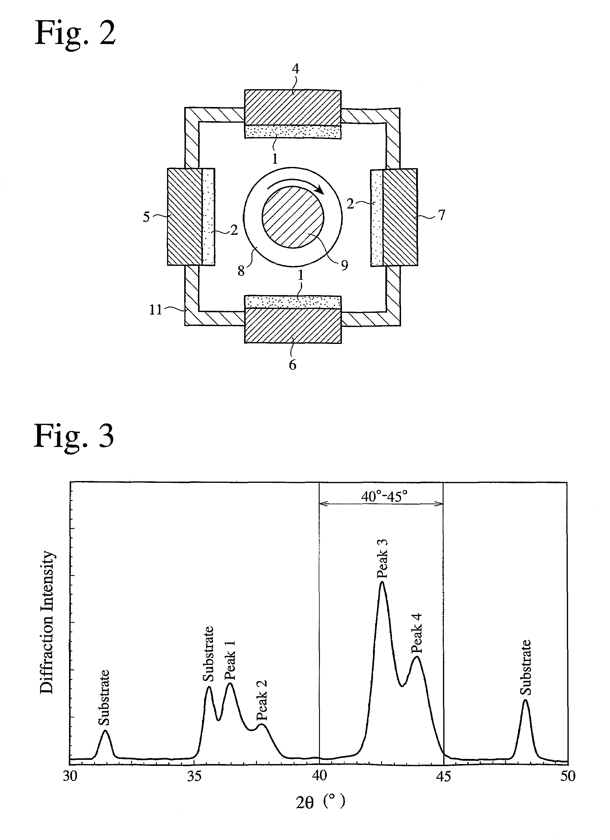
[0061]The formation of a hard coating was conducted using an AIP apparatus shown in FIG. 2. The AIP apparatus comprises a vacuum chamber 11, pluralities of arc-discharge evaporators 4-7 disposed on an inner wall of the vacuum chamber 11, and a substrate holder 8 disposed on a bottom of the vacuum chamber 11. The arc-discharge evaporators 4-7 are insulated from the wall of the vacuum chamber 11. Each arc-discharge evaporator 4, 6 is provided with a target 1 for forming a metal component of the lowermost layer in the hard coating, and each arc-discharge evaporator 5, 7 is provided with a target 2 for forming a metal component of the uppermost layer in the hard coating. Arc discharge is generated on the targets 1 and / or 2 by supplying predetermined current to each arc-discharge evaporator 4-7, to evaporate and ionize the metal component, and metals were vapor-deposited from the targets 1 and / or 2 onto a substrate 9 placed on the substrate holder 8 by applying a b...

example 2

[0085]A hard coating corresponding to each Sample 1-38 of Example 1 was formed on a substrate of a 6-mm-diameter, high-speed-steel drill (cutting evaluation 1), and on a substrate of a two-edge cemented carbide ball end mill (cutting evaluation 2), respectively, and their cutting performance was evaluated under the following conditions. The layer-forming conditions of each Experiment were the same as in Example 1 unless otherwise particularly described, and the experiment numbers corresponds to the sample numbers in Example 1. The evaluation results are shown in Table 4.

[0086](a) Conditions of Cutting Evaluation 1

[0087]Work: SCM440 (HRC 30),

[0088]Rotation speed of tool: 3200 rpm,

[0089]Feed per one rotation: 0.15 mm,

[0090]Cutting depth: 15 mm, unpenetrating hole,

[0091]Cutting method: Using an externally supplied aqueous cutting liquid, and

[0092]Determination of life: Counting the number of drilled holes until further drilling became impossible (less than 100 holes were omitted).

[0093...

example 3

[0108](1) Production of Sample 41

[0109]Targets used for forming the layers of Sample 41 were metal targets produced by a powder metallurgy method. As shown in FIG. 7, a target 1 of Al60Cr37Si3 (atomic %) was attached to each arc-discharge evaporator 4, 6, a target 2 of Ti100 was attached to the arc-discharge evaporator 5, and a target 3 of Cr90Si5B5 (atomic %) was attached to the arc evaporator 7.

[0110](a) Formation of Lowermost Layer

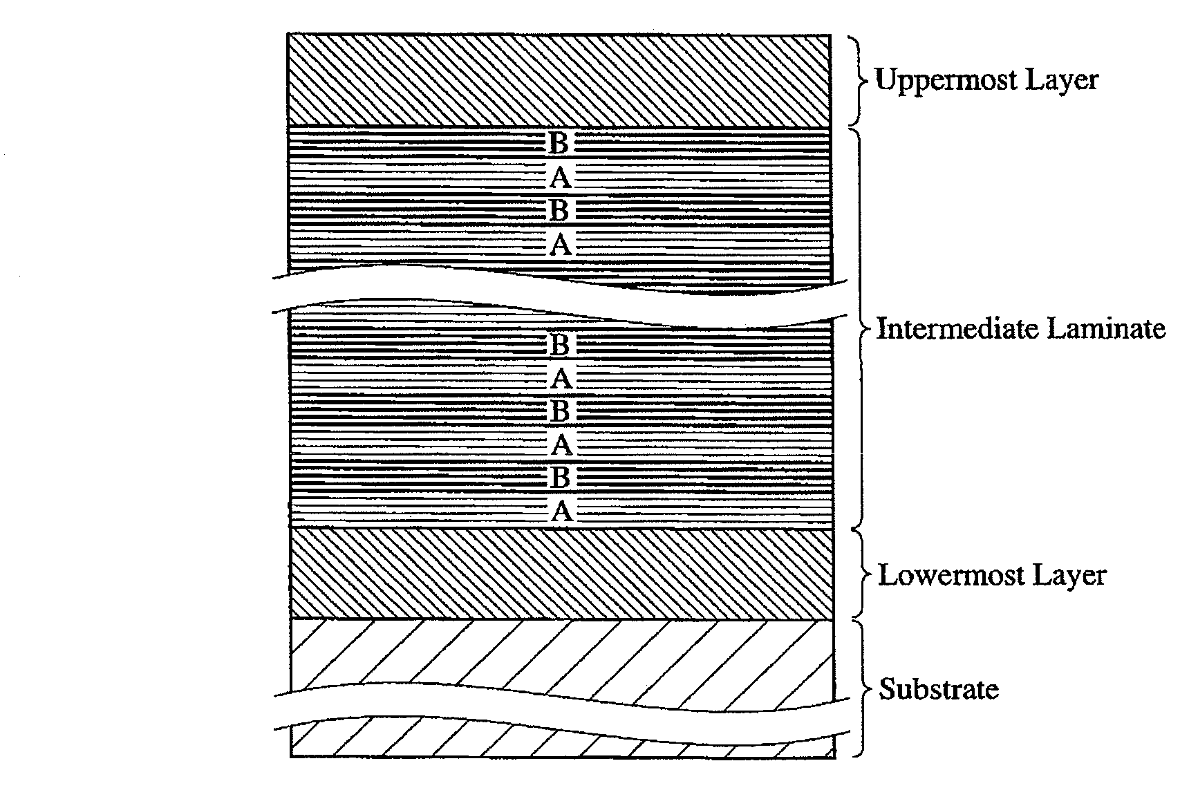
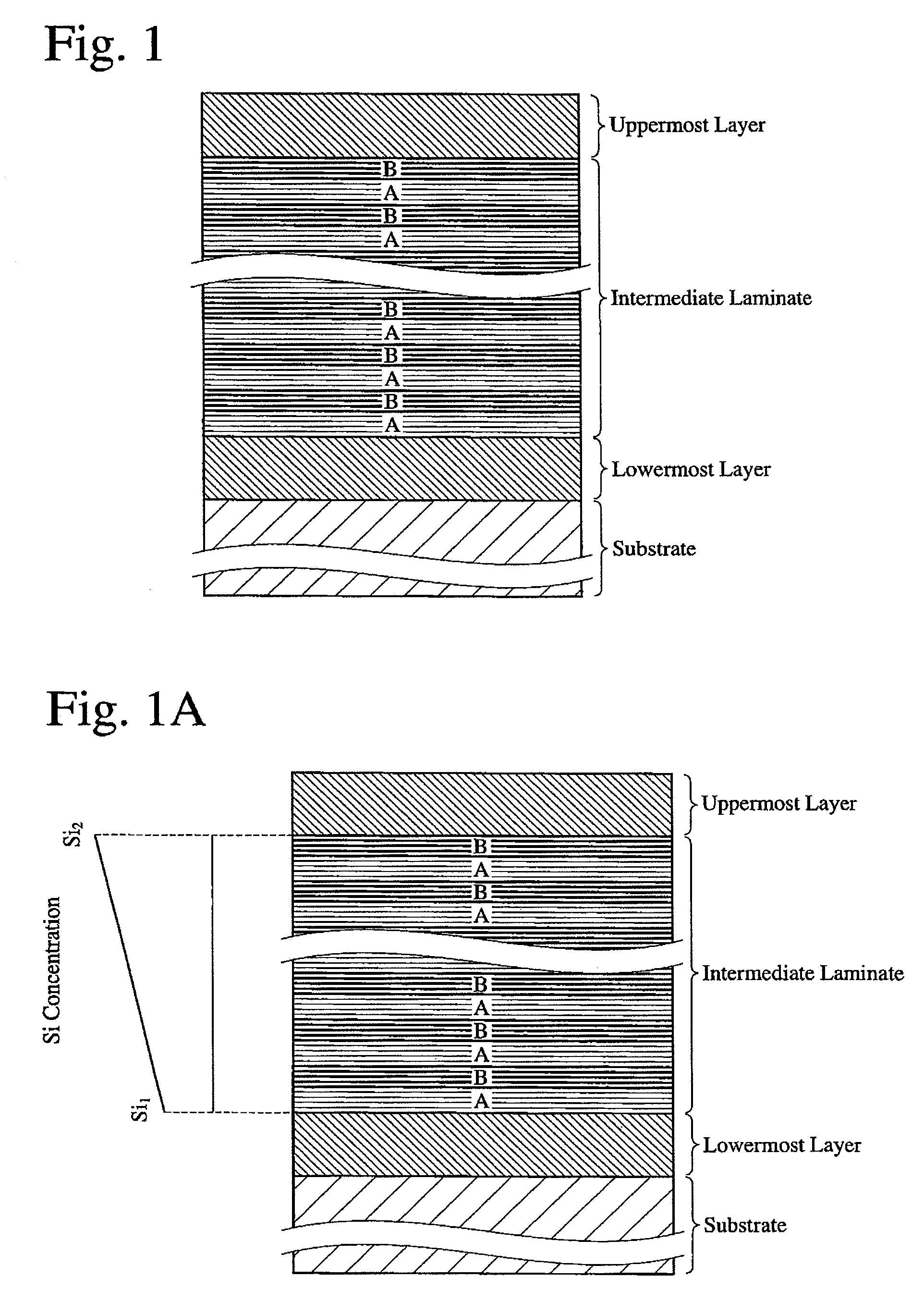
[0111]Supplying current (25 V, 100 A) to the evaporator provided with the target 1, a lowermost nitride layer of about 200 nm was formed on a substrate surface under the conditions of a negative-bias voltage of 100 V, a reaction gas pressure of 4 Pa, a substrate temperature of 500° C., and a substrate-rotating speed of 3 rpm. Though the composition of the target 1 was Al60Cr37Si3, the metal component composition of the vapor-deposited lowermost layer was Al57Cr41Si2.

[0112](b) Formation of Intermediate Laminate

[0113]A nitride layer was formed on the lowe...


PUM

PropertyMeasurementUnit
thicknessaaaaaaaaaa
aaaaaaaaaa
bonding energyaaaaaaaaaa

Abstract

A hard-coated member comprising a hard coating comprising a lowermost layer, an intermediate laminate and an uppermost layer on a substrate, the intermediate laminate being constituted by alternately laminated layers A and layers B having different compositions, the layers A and the layers B being respectively made of at least one selected from the group consisting of nitrides, borides, carbides and oxides of metal components having compositions represented by the formula of AlWCrXTiYSiZ, wherein W, X, Y and Z respectively represent atomic % of Al, Cr, Ti and Si, W+X+Y+Z=100, and these combinations, the layers A meeting the condition of 70≦W+X<100, the layers B meeting the condition of 30≦Y<100, and the uppermost layer being made of at least one selected from the group consisting of nitrides, carbides, sulfides and borides of Ti or Ti and Si and these combinations, or at least one selected from the group consisting of nitrides, carbides, sulfides and borides of Cr or Cr and Si and these combinations.

Description

FIELD OF THE INVENTION[0001]The present invention relates to a hard-coated member having not only excellent lubrication and resistance to peeling from a substrate, but also excellent seizure resistance and / or wear resistance, which is suitable as members requiring high hardness, such as cutting tools, molding dies, bearings, forming dies, rolls, etc.BACKGROUND OF THE INVENTION[0002]Cutting tools, etc. are provided with single- or multi-layer hard coatings made of carbides, nitrides and carbonitrides of Al, Cr, Ti and Si, or oxides of Al, etc., to improve hardness, wear resistance, lubrication, seizure resistance, etc. Particularly because coatings of composite nitrides of Ti and Al (TiAlN) exhibit excellent wear resistance, they are formed on cutting tools of high-hardness materials such as high-speed steel, hardened steel, etc.[0003]JP 2003-71610A discloses a cutting tool having a multi-layer coating, as a hard coating having higher wear resistance than TiAlN, which is formed by al...

Claims


Application Information

Patent Timeline
Patent Type & Authority Patents(United States)
IPC IPC(8): B32B9/00
CPCC23C14/06C23C14/0623C23C14/0641C23C14/0664C23C14/325C23C14/3492C23C28/04C23C30/005C23C14/0676Y10T428/24942C23C14/00C23C28/00C22C21/00
Inventor ISHIKAWA, TAKESHI
Owner HITACHI TOOL ENG LTD
Why Eureka
Try Eureka