
Resin casting mold and method of casting resin

a resin casting and mold technology, applied in the direction of dough shaping, manufacturing tools, applications, etc., can solve the problems of reducing driving efficiency, unable to provide smaller resin casting equipment including molds, so as to achieve high driving efficiency and large size

Inactive Publication Date: 2006-06-22
TOWA
View PDF4 Cites 11 Cited by
  • Summary
  • Abstract
  • Description
  • Claims
  • Application Information

AI Technical Summary

Benefits of technology

[0021] The present invention solves the above problems. An object of the present invention is to provide a resin casting mold and a method of casting a resin in which a thinner casting product with a larger major surface can be properly separated from a cavity surface without damaging the casting product and with high driving efficiencies and without equipment including a resin casting mold with a complicated structure or a large size.
[0025] According to the present invention, the casting product is separated from the resin casting mold without ejecting the casting product, in other words, without applying a force in the thickness direction of the casting product. This provides the following advantages: A mechanism to eject a casting is not necessary, resulting in a simplified structure of equipment including a resin casting mold. Also, the stress in the thickness direction of the casting product is reduced, such that the quality of casting products, especially those with a large major surface and smaller thickness, is less likely to be adversely affected. Further, a shearing stress is effected across the sticking plane between the cured resin and the cavity, making it easier to separate the casting product from the resin casting mold.
[0027] Thus, with the cured resin sticking to the bottom surface, a shearing stress and a tensile stress between the bottom surface and the cured resin act to separate the cured resin from the bottom surface, making it easier to remove the casting product off the cavity.

Problems solved by technology

Unfortunately, the above conventional techniques have the following problems:
A mechanism using an ejector pin to eject the casting requires a space in which the ejector plate can be moved upward and downward, making it impossible to provide smaller resin casting equipment including a mold.
A mechanism in which high pressure fluid is jetted toward the casting requires a compressor, a high-pressure fluid tank, tubing and more, again making it impossible to provide smaller resin casting equipment including a mold.
A mechanism in which the resin casting mold is vibrated to remove the casting off the cavity surface requires vibration to occur throughout the entire resin casting mold rather than merely where the casting sticks to the cavity surface, which leads to lower driving efficiencies and also results in resin casting equipment including a resin casting mold with a complicated structure.
Further, some fluid resins have properties that may prevent a casting product including a cured resin from being efficiently separated from the cavity surface when, for example, the cured resin firmly sticks to the cavity surface.
In the case that a piezoelectric material is deformed in a direction that lies along the cavity surface from the center of the cavity toward the outside, it is difficult to reduce the degree of sticking of the casting to the cavity surface around the center of the cavity.
When the piezoelectric material is deformed in a direction crossing the cavity surface, the deformation of the piezoelectric material may damage the casting, which would reduce the quality of the casting.
The above gives rise to the following application-specific problems:
For example, a mechanism with an ejector pin may cause a crack in a thinner casting product (board and cured resin).
Breaking or improper connection may also occur in wires connecting the chip and the board.
All this contributes to reduced reliability and yield of the end product, i.e. electronic component.
Moreover, larger major surface of the casting product requires increased number of ejector pins, resulting in equipment including a resin casting mold with a complicated structure.
Consequently, a crack may occur in thinner casting products.
Moreover, increasing the number of holes through which the high pressure fluid is jetted toward the casting product results in equipment including a resin casting mold with a complicated structure, similar to the case of increasing the number of ejector pins.
In a mechanism with a vibrated resin casting mold, separating the casting product off the cavity surface becomes more difficult as the major surface of the casting product and the degree of sticking of the cured resin to the cavity surface are increased.
Further, since the vibration is externally applied to the resin casting mold, the cured resin in the cavity and the resin casting mold belong to the same vibration system, which means that an increased amplitude provides substantially no improvement in the separation of the cured resin since the shearing force acting upon the sticking plane between the cavity surface and the casting product is derived solely from inertial force from the vibration.
In the case that the piezoelectric material providing the cavity surface is deformed, it becomes more difficult to separate the casting product from the resin casting mold as the major surface of the casting product and the degree of sticking of the cured resin to the cavity surface are increased.
Further, deforming the piezoelectric material in a direction crossing the cavity surface may cause a crack in a thinner casting product.

Method used


Image

  • Resin casting mold and method of casting resin
  • Resin casting mold and method of casting resin
  • Resin casting mold and method of casting resin

Examples


first embodiment

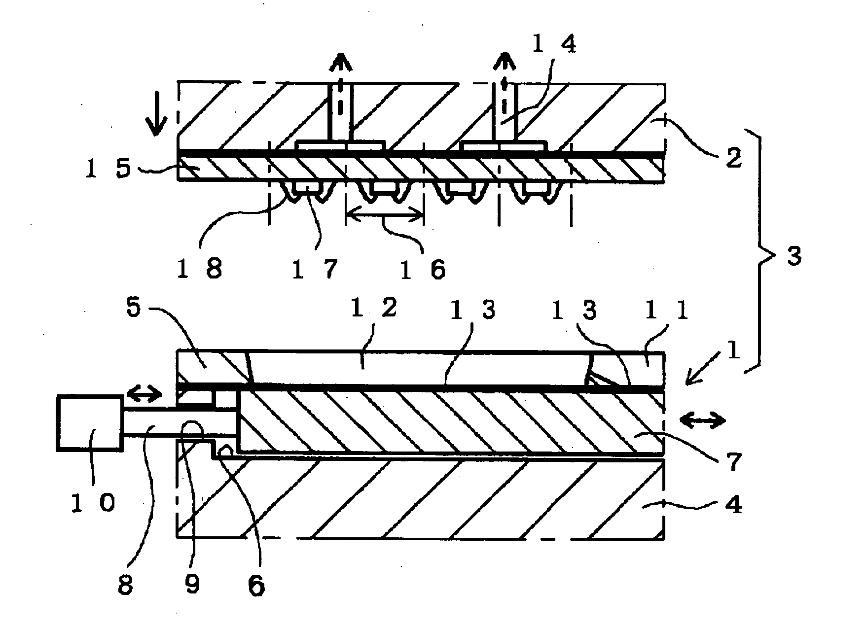
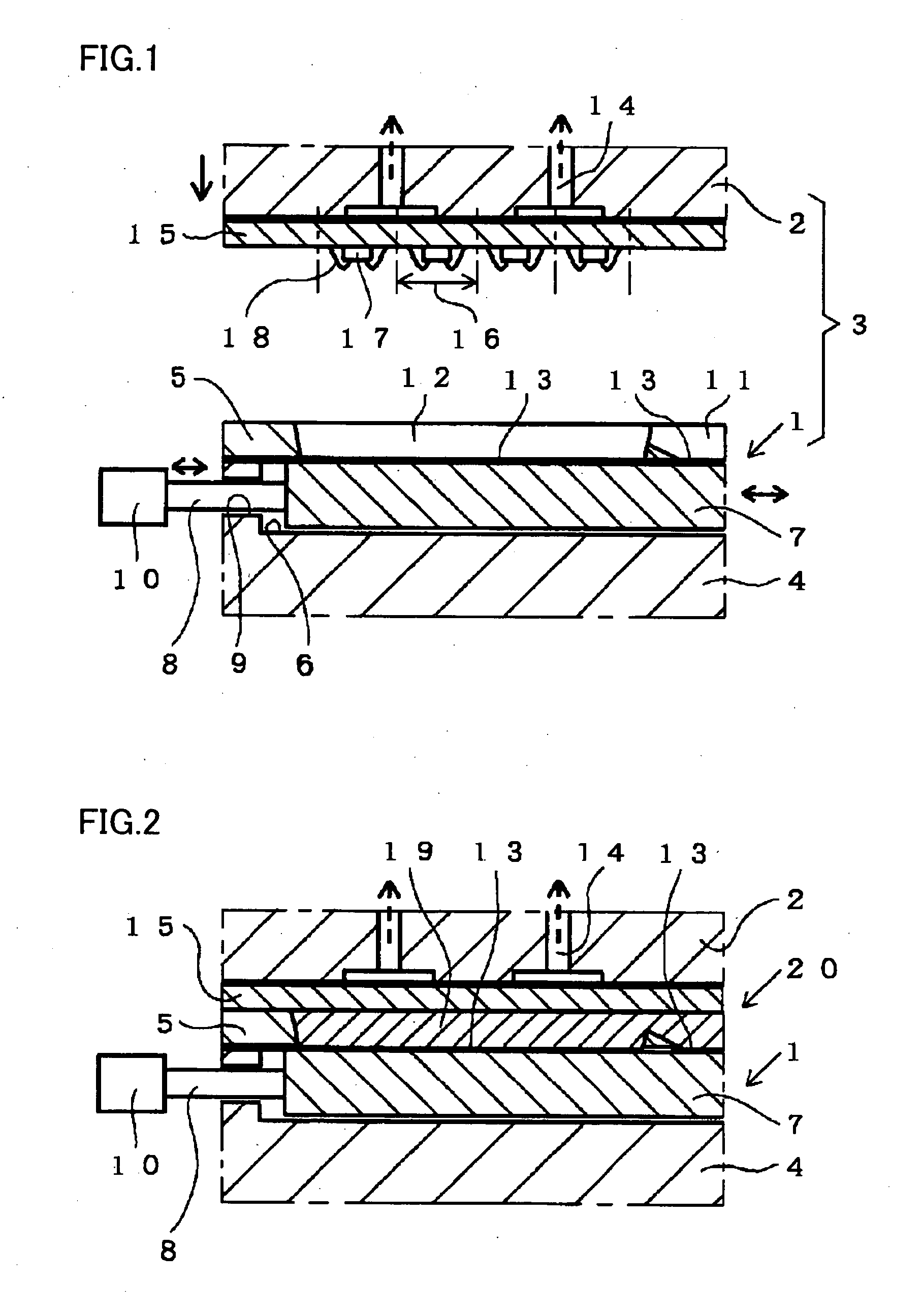
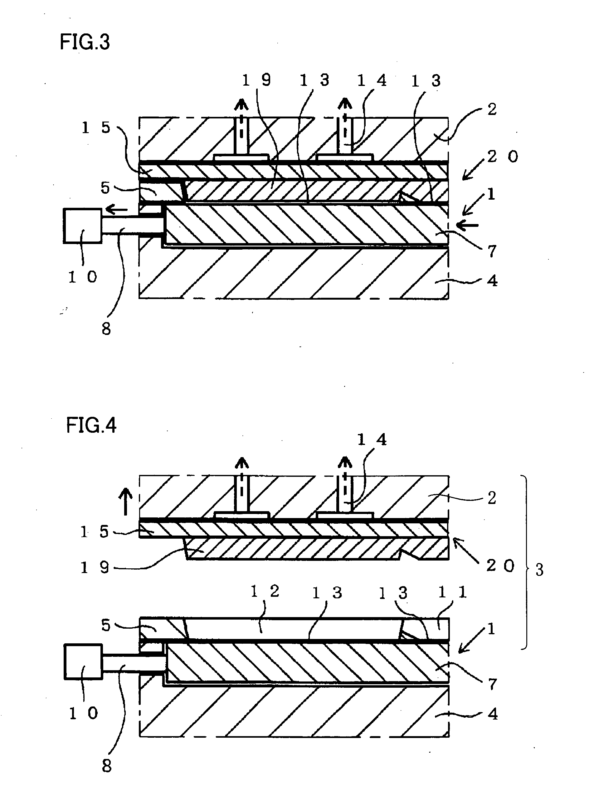
[0034] First, referring to FIGS. 1 to 4, a resin casting mold and a method of casting a resin according to a first embodiment of the present invention will be described. Description will be made of a method of casting a resin for manufacturing a package for a plurality of electronic components where transfer molding is employed to resin-seal a plurality of chips mounted on one board. Thus, a casting product of the present invention is a group of a plurality of packages of the present embodiment.

[0035] As shown in FIG. 1, a resin casting mold 3 of the present embodiment includes a lower mold 1 and an upper mold 2 opposite to lower mold 1, and is used in resin-sealing employing transfer molding.

[0036] Lower mold 1 includes a base 4, an opposing member 5 secured to base 4 and opposite to upper mold 2, a recess 6 provided in base 4, and a block 7 placed within recess 6 and slidable in a horizontal direction. A rod 8 is secured to a side of block 7 and to a driver mechanism 10 via a ho...

second embodiment

[0052] Now, referring to FIGS. 3 and 4, a resin casting mold and a method of casting a resin according to a second embodiment of the present invention will be described. The method of the present embodiment is characterized by opening lower and upper molds 1 and 2 during the step shown in FIG. 3, i.e. the step of using driver mechanism 10 to move block 7 in a horizontal direction (to the left in the figures).

[0053] Preferably, the opening of lower and upper molds 1 and 2 begins directly after block 7 begins to be moved in the case of a thinner casting product 20 with a larger major surface, i.e. when it is required to minimize the stress upon casting product 20 during the separation of casting product 20 from resin casting mold 3.

[0054] The method of casting a resin of the present embodiment described above achieves proper separation for casting product 20 since a shearing stress and a tensile stress act between bottom surface 13 and the lower surface of cured resin 19 with the lo...


PUM

PropertyMeasurementUnit
Forceaaaaaaaaaa

Abstract

A resin casting mold used for manufacturing a casting product including a cured resin produced by curing a fluid resin filling a cavity includes: a block providing the bottom surface of the cavity; and a driver mechanism for applying a force to the block to move the block in a direction that lies along the bottom surface. The driver mechanism moves the block when the cured resin has been formed to separate the cured resin from the bottom surface. This arrangement allows a thinner casting product with a larger major surface to be properly separated from the cavity surface without damaging the casting product and with high driving efficiencies and without equipment including a resin casting mold with a complicated structure or a large size.

Description

[0001] This nonprovisional application is based on Japanese Patent Application No. 2004-365973 filed with the Japan Patent Office on Dec. 17, 2004, the entire contents of which are hereby incorporated by reference. BACKGROUND OF THE INVENTION [0002] 1. Field of the Invention [0003] The present invention relates to a resin casting mold and a method of casting a resin where a fluid resin filling a cavity is cured to produce a casting product. [0004] 2. Description of the Background Art [0005] Conventionally, a resin casting mold is employed for manufacturing castings by curing a fluid resin filling a cavity. Such a mold provides a cured resin within a cavity, thereby providing a casting product including the cured resin. [0006] Subsequently, the casting product is removed from the mold. For this purpose, an ejector mechanism (see Japanese Utility Model Laying-Open No. 2-36039, FIG. 9, for example) is utilized, which includes: an ejector plate(s) separate from the mold below and / or abo...

Claims


Application Information

Patent Timeline
IPC IPC(8): B29C41/42
CPCB29C39/36B29C41/42B29C43/18B29C45/14639B29C45/40H01L21/565H01L24/97H01L2224/48227H01L2224/97H01L2224/85H01L2924/01005H01L2924/01006H01L2924/01033H01L2924/181H01L2924/00B29C33/00B29C33/12
Inventor KUNO, TAKAKIMAEDA, KEIJI
Owner TOWA
Learn More