Device and method for starting brushless direct current motor

a direct current and motor technology, applied in the direction of motor/generator/converter stopper, electronic commutator, dynamo-electric converter control, etc., can solve the problem of increasing the startup failure rate, the position of the rotor cannot be effectively detected, and the startup noise and vibration are high, so as to reduce the startup noise and vibration and the startup failure rate

Active Publication Date: 2006-06-22
SAMSUNG ELECTRONICS CO LTD
View PDF23 Cites 14 Cited by
  • Summary
  • Abstract
  • Description
  • Claims
  • Application Information

AI Technical Summary

Benefits of technology

[0013] It is an aspect of the invention to provide a method and device for starting a BLDC motor, in which startup noise and vibration and startup failure rate can be reduced using a constant low-speed startup scheme when the BLDC motor is in sensorless startup mode.

Problems solved by technology

However, the position of the rotor cannot be detected effectively if the motor runs at low speed.
That is, since the position of the rotor cannot be detected when the BLDC motor is in sensorless startup mode, a drive signal must be generated in a manner different from conventional driving methods.
However, in the conventional BLDC motor starting method, since the PWM duty is constantly increased even though rotor position detection is not performed normally, the rotor position and the phase commutation time may become desynchronized depending on changes in the load torque of the BLDC motor, and the startup current may become excessively high, thereby causing high startup noise and vibration.
In addition, since the conventional BLDC motor starting method increases the rotor speed as described above, the rotor position and the phase commutation time may be desynchronized, increasing the startup failure rate, if the conventional BLDC motor starting method is applied to a system such as a compressor, whose load torque increases as the rotor speed increases.
Also, an excessive startup current may occur, making it difficult to optimize specifications of the inverter.

Method used


Image

  • Device and method for starting brushless direct current motor
  • Device and method for starting brushless direct current motor
  • Device and method for starting brushless direct current motor

Examples


Embodiment Construction

[0041] Reference will now be made in detail to the exemplary embodiments of the present invention, examples of which are illustrated in the accompanying drawings, wherein like reference numerals refer to the like elements throughout. The exemplary embodiments are described below to explain the present invention by referring to the figures.

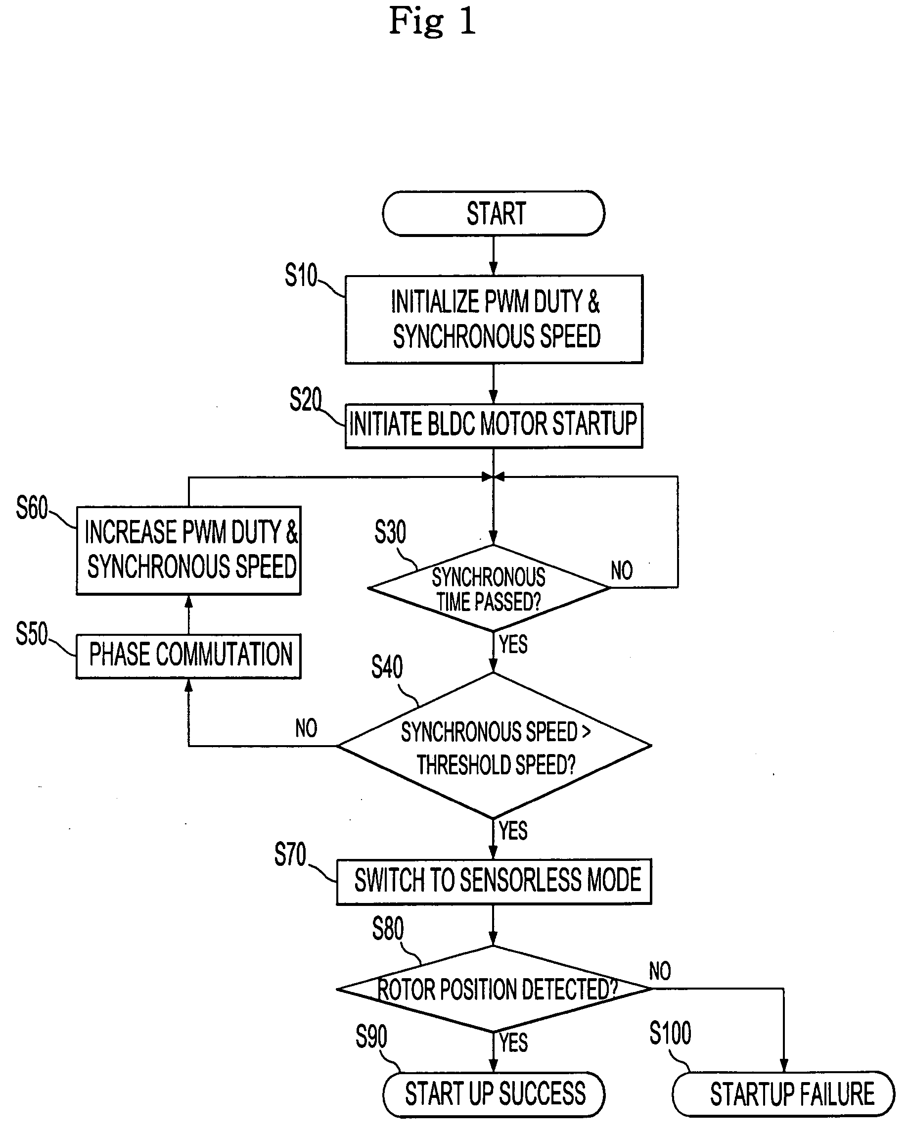
[0042] As shown in FIG. 3, a sensorless BLDC motor starting device according to an exemplary embodiment of the present invention comprises a power source 10, an AC-to-DC power converter 30, an inverter 50, a terminal voltage detector 90, and a controller 100. The power source 10 supplies commercial AC power, and the converter 30 converts the AC power into DC power. The inverter 50 converts the DC power output from the converter 30 into three-phase AC power by alternately turning on and off a plurality of power transistors in order to rotate a BLDC motor 70. The terminal voltage detector 90 detects a back EMF in the BLDC motor 70 to detect a rotor ...


PUM


Abstract

A Brushless Direct Current (BLDC) motor starting method and device are provided, in which startup noise and vibration and startup failure rate can be reduced using a constant low-speed startup scheme when the BLDC motor is in sensorless startup mode, and PWM duty is also maintained at low level when the BLDC motor starts up, thereby preventing an excessive current from occurring due to desynchronization of the motor at startup, so that it is possible to optimize specifications of an inverter in the BLDC motor. The BLDC motor starts up with a startup speed and a PWM duty of a rotor of the BLDC motor being kept constant, and the BLDC motor switches to sensorless mode if a position of the rotor is detected a predetermined number of times or more during a specific time.

Description

CROSS-REFERENCE TO RELATED APPLICATION [0001] This application claims priority from Korean Patent Application No. 2004-109736, filed on Dec. 21, 2004 in the Korean Intellectual Property Office, the disclosure of which is incorporated herein by reference. BACKGROUND OF THE INVENTION [0002] 1. Field of the Invention [0003] Apparatuses and methods consistent with the present invention relate to starting a Brushless Direct Current (BLDC) motor, and more particularly, to a device and method for starting a BLDC motor, in which a startup current is maintained at low level when the BLDC motor starts up, thereby reducing startup noise and vibration and startup failure rate. [0004] 2. Description of the Related Art [0005] Generally, a sensorless BLDC motor includes a stator on which a coil is wound and a rotor that is provided in the stator and rotates to drive a load. The position of a rotor is detected based on a back electromotive force (EMF) appearing on coil terminals, and a voltage appl...

Claims


Application Information

Patent Timeline
Patent Type & Authority Applications(United States)
IPC IPC(8): H02P1/18H02P7/06
CPCH02P6/205H02P6/21H02P6/20
Inventor OH, KWANG KYOHAMAOKA, KOJIYOO, HAN JOOPARK, PYEONG KIBAE, HUN YUBKIM, YUN JEONGSEO, JEONG HO
Owner SAMSUNG ELECTRONICS CO LTD
Why Eureka
Try Eureka