Power amplifying apparatus

a technology of power amplifying apparatus and amplifier, which is applied in the direction of amplifier, dc amplifier with modulator-demodulator, amplifier, etc., to achieve the effect of reducing power consumption, reducing power consumption advantageously, and reducing power consumption

Inactive Publication Date: 2006-06-22
PANASONIC CORP
View PDF9 Cites 58 Cited by
  • Summary
  • Abstract
  • Description
  • Claims
  • Application Information

AI Technical Summary

Benefits of technology

[0048] According to the present invention, even though the power supply voltage Vc alternately varies, the gain of the power amplifying apparatus is not adversely affected, and the output AC signal can be advantageously prevented from being distorted by the variation of the power supply voltage Vc. The decrease in gain by a DC voltage component Ec of the power supply voltage can reduce the effective values of currents flowing in the switch circuits that drive the load in the power amplifying apparatus, and the power consumption can be advantageously reduced. The DC voltage component Ec of the power supply voltage Vc in the switch circuit constituted by the series circuit of the high-side switch and the low-

Problems solved by technology

In addition, when a power is supplied through a stabilizing power supply unit, a detection voltage which is fed back to stabilize the output voltage is

Method used


Image

  • Power amplifying apparatus
  • Power amplifying apparatus
  • Power amplifying apparatus

Examples


first embodiment

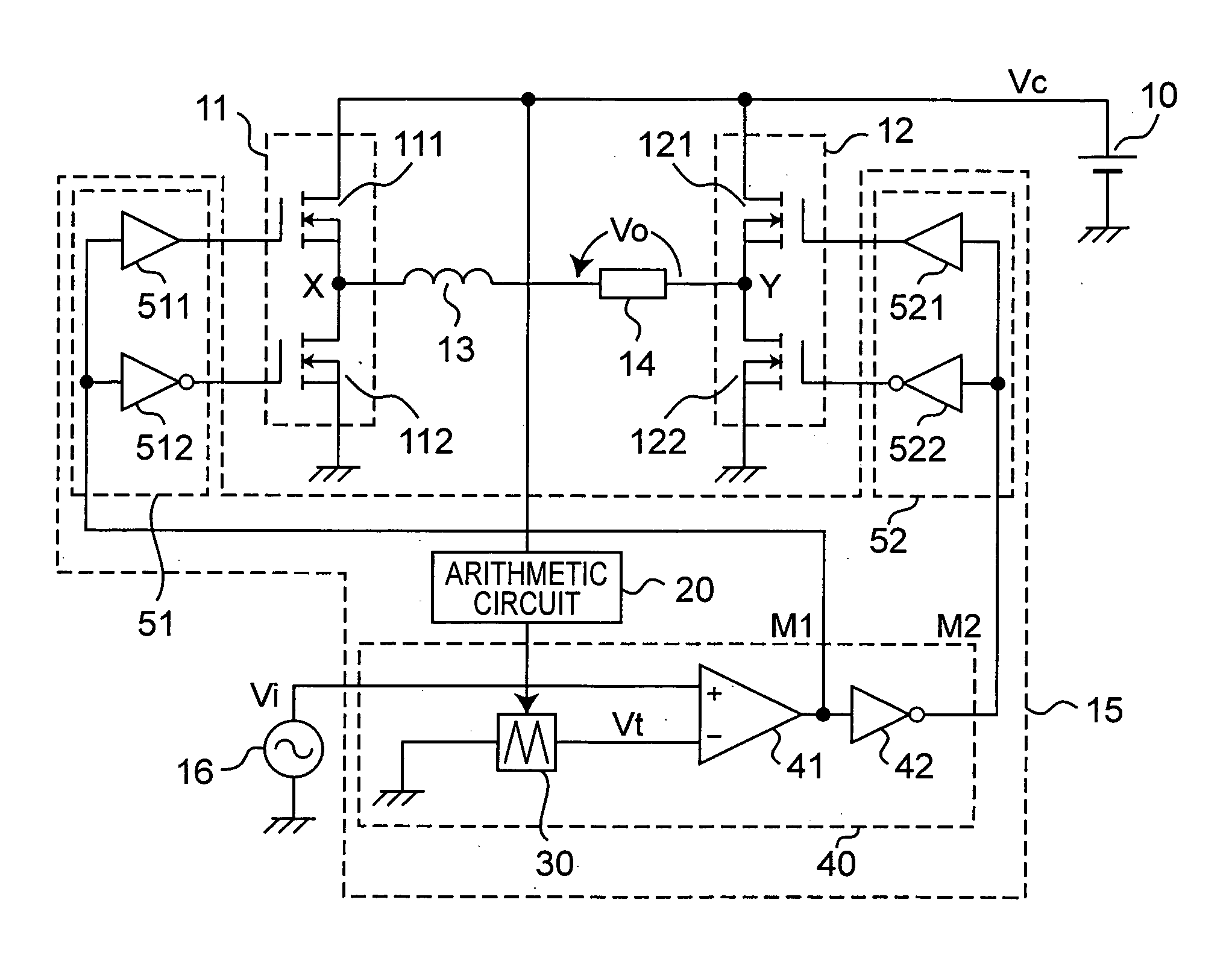
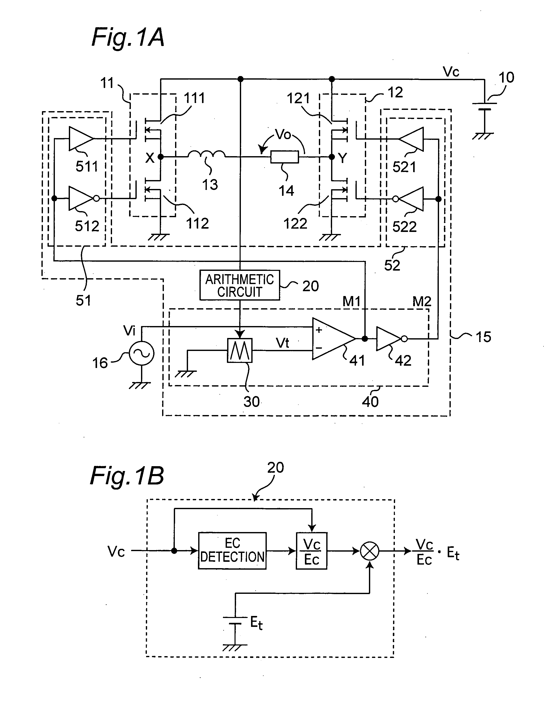
[0066]FIG. 1A shows a circuit configuration of a power amplifying apparatus according to the first embodiment.

[0067] The power amplifying apparatus includes first and second switch circuits 11 and 12 and a control circuit 15 that controls the operations of these switch circuits. The control circuit 15 has first and second drive circuits 51 and 52 that drive the first and second switch circuits 11 and 12, respectively, an arithmetic circuit 20 that detects a power supply voltage Vc to output a predetermined voltage, and a pulse width control circuit 40.

[0068] The first switch circuit 11 receives a power supply voltage Vc from a DC power supply 10 and includes a first high-side switch 111 and a first low-side switch 112 that are N-channel MOSFETs on one side of an H-shaped bridge configuration switch circuit. Similarly, the second switch circuit 12 includes a second high-side switch 121 and a second low-side switch 122 that are N-channel MOSFETs. A series circuit of an inductor 13 a...

second embodiment

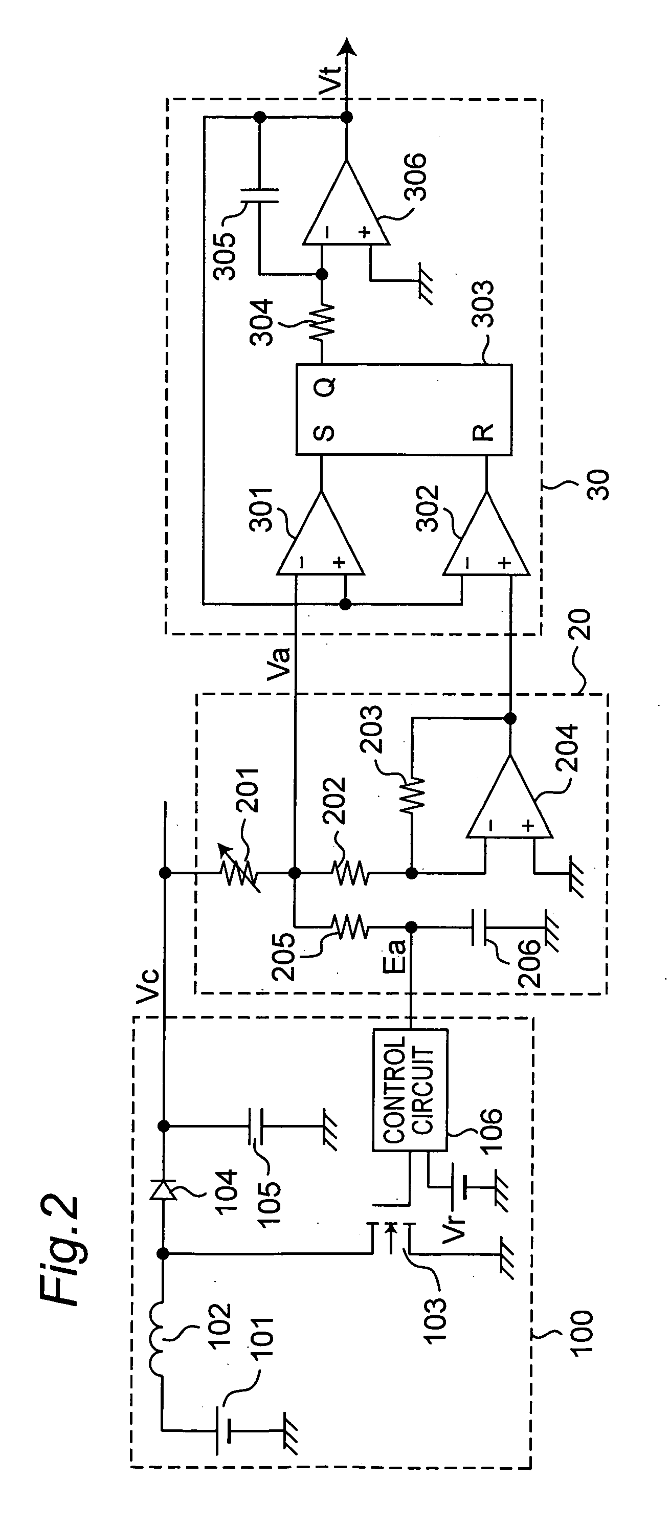
[0085]FIG. 2 shows the circuit configuration of a main part of a power amplifying apparatus according to the second embodiment. The same reference numerals as in the power amplifying apparatus of the first embodiment shown in FIG. 1 denote the same elements in FIG. 2. Furthermore, since the drive circuits 51 and 52, the switch circuits 11 and 12 of the H-shaped bridge configuration, the load 14, and the like are substantially the same as those in FIG. 1, these elements are omitted. The configuration in FIG. 2 is different form that in FIG. 1 in that a DC-DC step-up converter (DC-DC converter) 100 which is arranged in place of the DC power supply 10 steps up and converts a voltage of a buttery 101 to supply a power supply voltage Vc. Further configurations of the arithmetic circuit 20 and the triangular wave voltage generation circuit 30 are described in detail. In addition, control of the amplitude of a triangular wave of the triangular wave voltage generation circuit 30 through the...

third embodiment

[0104]FIG. 3 shows the circuit configuration of a main part of the power amplifying apparatus according to the third embodiment. The same reference numerals as in the power amplifying apparatus of the second embodiment shown in FIG. 2 denote the same constituent elements in FIG. 3. The circuit configuration following a triangular wave voltage generation circuit 30 may be the same as that in FIG. 2. Furthermore, the configuration including a drive circuit, an H-shaped bridge configuration switch circuit, a load unit, and the like which follow a PWM circuit 40 may also be the same substantially as that in FIG. 1. Hence these components are omitted in the drawing. The circuit configuration in FIG. 3 is different from the circuit configuration in FIG. 2 in the internal configuration of an arithmetic circuit 20.

[0105] An operation of the power amplifying apparatus according to the embodiment shown in FIG. 3 will be described below.

[0106] In a step-up converter 100, a series circuit of ...


PUM


Abstract

A power amplifying apparatus which is of a switching type and capable of efficiently amplifying a power of an input AC signal such as an acoustic signal, includes a first switch circuit (11) and a second switch circuit (12) to which a power supply voltage Vc is applied, an inductor (13) and a load (14) which are connected between the switch circuits, and a control circuit (15) which receives an input AC signal Vi, sets a predetermined ratio of ON/OFF periods, and drives the switch circuits. The control circuit (15) includes an arithmetic circuit (20) which multiplies a modulation sensitivity (for example, an amplitude of a triangular wave voltage used for generation of a pulse signal for driving a switch circuit) by a ratio (Vc/Ec) of the power supply voltage Vc and a DC component Ec thereof. This configuration can compensate for distortion caused by a ripple variation of the power supply voltage due to regenerated power or the like, and enable a gain control by the power supply voltage.

Description

TECHNICAL FIELD [0001] The present invention relates to a power amplifying apparatus that amplifies the power of an input AC signal obtained from an acoustic signal to apply it to an electric acoustic converter such as a loudspeaker, and more particularly, to a compensation art for power supply voltage variation in a power amplifying apparatus having a D-class amplification function to an input AC signal. BACKGROUND ART [0002] In driving an acoustic speaker, a linear power amplifying apparatus such as an A-class, B-class, or AB-class amplifying apparatus having a simple configuration is used popularly. In such a linear power amplifying apparatus, a power loss of the power amplifying apparatus itself is large in an operational principle, and heat generated by a power consumption of the power amplifying apparatus itself increases according to an increase in output power. For this reason, a large heat sink to diffuse the heat is disadvantageously necessary. Therefore, as a power amplif...

Claims


Application Information

Patent Timeline
IPC IPC(8): H03F3/38H03F1/02H03F1/32H03F3/217
CPCH03F1/0211H03F1/3205H03F3/2173H03F2200/331
Inventor ISHII, TAKUYAIKEDA, MASAHARUAKASHI, HIROKI
Owner PANASONIC CORP
Why Eureka
Try Eureka