Apparatus for detecting direction of target using difference in phase of radio wave signals received through plural channels

a radio wave signal and antenna technology, applied in the direction of using reradiation, measuring devices, instruments, etc., can solve the problems of incompleteness of the foregoing erroneous detection, inability to distinguish =sub>0/sub>, and inability to detect =sub>0/sub>, so as to prevent erroneous detection of targets

Active Publication Date: 2006-06-22
DENSO CORP
View PDF3 Cites 27 Cited by
  • Summary
  • Abstract
  • Description
  • Claims
  • Application Information

AI Technical Summary

Benefits of technology

[0024] Hence, when the imaging device is provided, the imaging device can be utilized to prevent erroneous detection of the targets resulting from the phase aliasing.

Problems solved by technology

In such a configuration, however, as shown in FIG. 2, because changes in the phase have periodicity, aliasing in the phase will be caused, thus making it impossible to distinguish Δθ=θ0(|θ0|0±2nπ (n=1, 2, . . . ).
However, this technique is still confronted with some difficulties.
One is incompleteness in the foregoing erroneous detection.
When the directivity of an antenna is desired to be narrowed, it is very difficult to design an antenna system such that a gain thereof is sharply changed between the inside and the outside of the direction area A0.
Thus it is impossible to completely shut down the radio waves coming from the region outside the directional area A0, thus making it difficult to avoid the erroneous detection without fail.
Another difficulty is a lowered performance of the antenna system.
When the arrangement interval between two antenna elements is made narrower, an aperture area of each antenna element will become insufficient.
This reduces the performance of the antenna system; for example, a maximum detection distance is lowered.
Further, a narrowed arrangement interval between the two antenna elements brings about another problem in the phased-array method and the DBF method.
However, since the arrangement interval between the antenna elements is made narrower, a very large number of antenna elements are required to obtain a certain necessary size of the aperture as the whole antenna array.
Thus both of labor for mounting the antenna elements and a manufacturing cost are obliged to be increased.
In the case that the apparatus employs the two antenna systems of which arrangement intervals differ from each other, the construction of the apparatus becomes complicated.

Method used


Image

  • Apparatus for detecting direction of target using difference in phase of radio wave signals received through plural channels
  • Apparatus for detecting direction of target using difference in phase of radio wave signals received through plural channels
  • Apparatus for detecting direction of target using difference in phase of radio wave signals received through plural channels

Examples


first embodiment

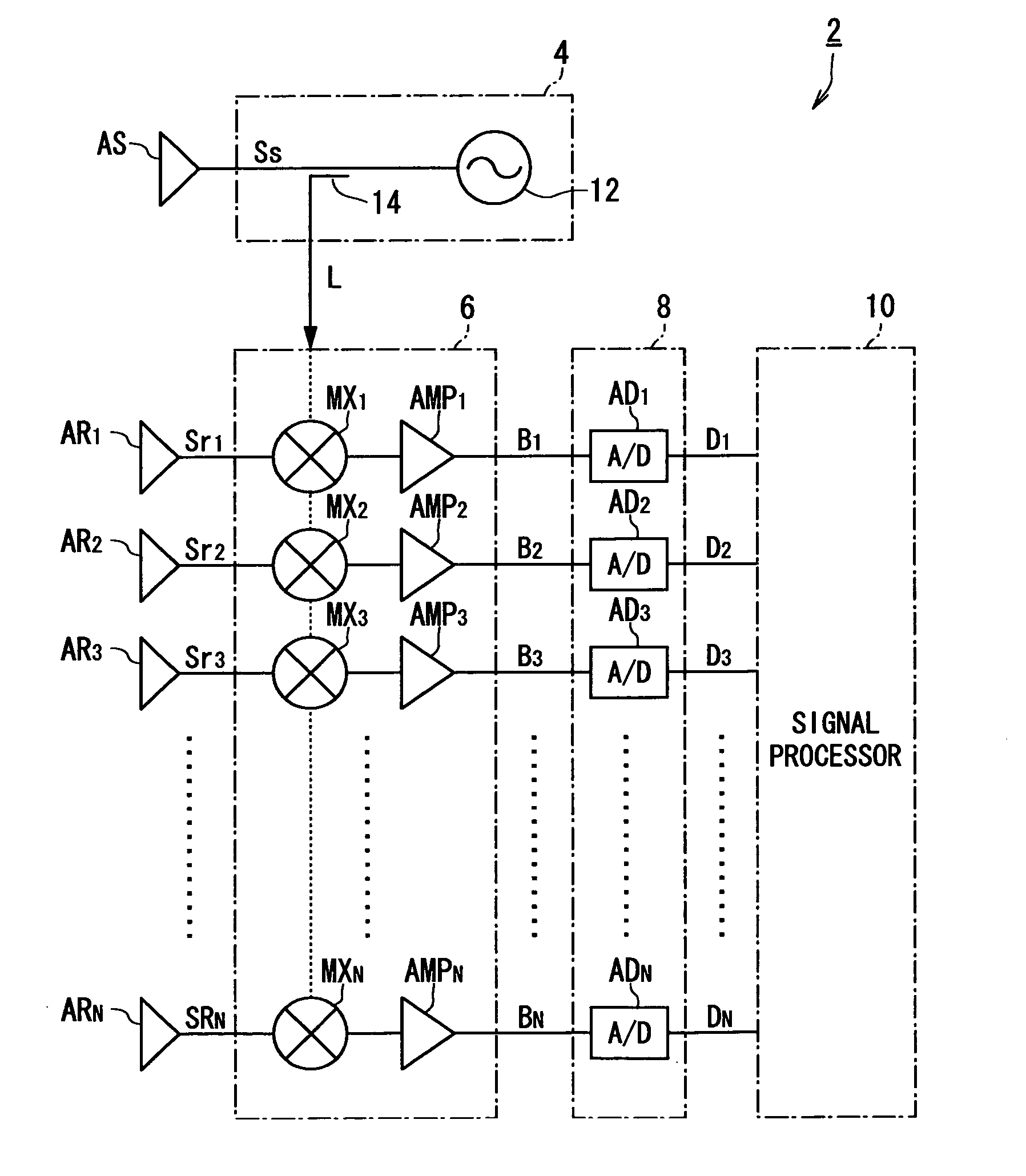
[0036]FIG. 5 shows in block form the entire configuration of an on-vehicle radar apparatus 2 according to the first embodiment.

[0037] As shown in FIG. 1, the radar apparatus 2 is equipped with a transmitter 4, an N-channel receiver 6, an N-channel A / D converter unit 8, and a signal processor 10.

[0038] The transmitter 4 is constructed to a millimeter wave-band radar wave via a transmission antenna AS. The receiver 6 is coupled with N-piece reception antennas AR1 to ARN arranged in line at equal intervals (in this embodiment, N=8). And the receiver 6 receives, through the reception antennas AR1 to ARN, a radar wave (hereafter referred to as reflected wave) transmitted by the transmitter 4 and reflected from landmark objects (barriers), such as leading vehicles and roadside objects, and produces N-piece beat signals B1 to BN, which will be detailed later.

[0039] The A / D converter unit 8 has N-piece A / D converters AD1 to ADN respectively receiving the beat signals B1 to BN produced by...

second embodiment

[0065] Referring to FIGS. 7 to 9, a second embodiment of the present invention will now be described.

[0066]FIG. 7 is a block diagram showing the entire configuration of a radar apparatus 2a according to the second embodiment.

[0067] This radar apparatus 2a differs from that explained in the first embodiment in only part of both the configuration and signal processing carried out by the signal processor 10, so that the same or identical components of the radar apparatus 2a as or to the radar apparatus 2 are given the same references.

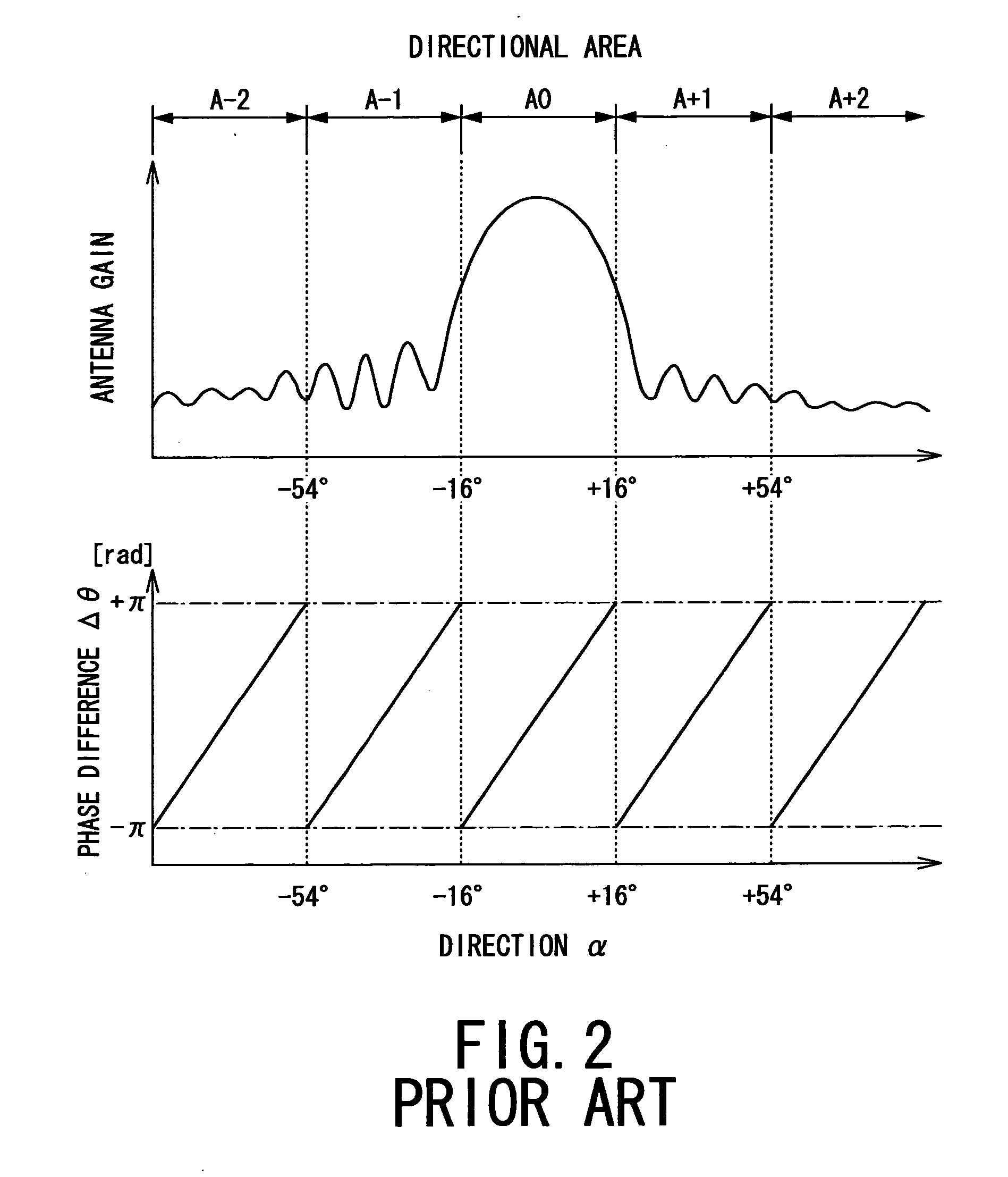
[0068] As shown in FIG. 7, in addition to the configurations of the radar apparatus 2 explained in the first embodiment, the radar apparatus 2a is provided with a CCD camera 16 capable of imaging an area wider than and including the directional area A0. Such a wider area ranges, for example, from −30 degrees to +30 degrees. The signal processor 10 is configured to perform target detecting processing to detect targets using digital data Di taken in throu...


PUM


Abstract

An apparatus for detecting a direction of a target is provided. The apparatus transmits and receives radio waves through a plurality of transmission/reception channels causing a phase difference in signals to be received through the transmission/reception channels and calculates the direction based on the phase difference. The apparatus comprises a direction calculating device, range determining device, and direction correcting device. The direction calculating device calculates the direction of the target based on the phase difference in the received signals on the assumption that the phase difference is within a range of −π to +π [rad]. The range determining device determines that the target exists in any of azimuthal angle ranges each corresponding to ranges defined by (2m−1)π to (2m+1)π [rad] (m is an integer). The direction correcting device corrects the direction according to a range-determined result.

Description

BACKGROUND OF THE INVENTION [0001] 1. Technical Field [0002] The present invention relates to an apparatus for detecting a direction of a target, and in particular, to the apparatus equipped with both of a plurality of channels of radio waves to be transmitted and received through antennas and means for detecting the direction of the target using a difference in phase of the radio wave signals received through the channels. [0003] 2. Related Art [0004] Among conventional techniques for detecting a direction of a target, one type of technique has been realized by using radio waves. Practically, such detection techniques have been known as a mono-pulse method, a phased array method, a digital beam forming (DBF) method, and others. These detection techniques use a difference in phase of signals received through a plurality of antenna elements. [0005] Specifically, as shown in FIG. 1A, these detection techniques require combinations of antenna elements (called “channels”), which give a ...

Claims


Application Information

Patent Timeline
Patent Type & Authority Applications(United States)
IPC IPC(8): G01S13/44G01S7/02G01S7/295
CPCG01S13/4463G01S13/723G01S13/867
Inventor NATSUME, KAZUMAKUMON, HIROAKIHOKI, KENTA
Owner DENSO CORP
Why Eureka
Try Eureka