
Structure and method for reducing thermal stresses on a torsional hinged device

a technology of torsional hinges and hinges, applied in the field of torsional hinges, can solve problems such as buckling and performance degradation, and achieve the effect of avoiding excessive compressive stresses on the torsional hinges of the devices

Active Publication Date: 2006-06-22
TEXAS INSTR INC
View PDF6 Cites 2 Cited by
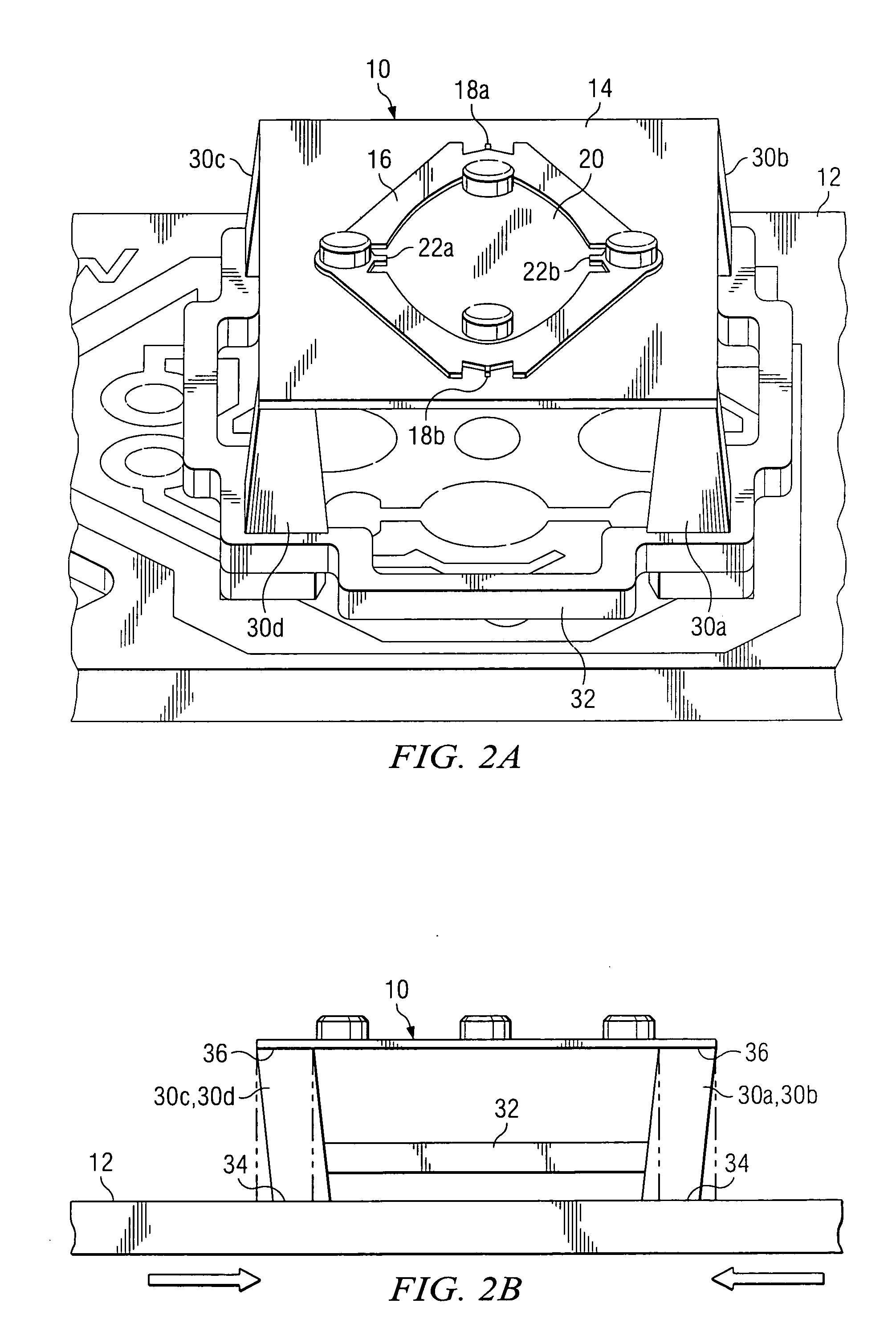
  • Summary
  • Abstract
  • Description
  • Claims
  • Application Information

AI Technical Summary

Benefits of technology

[0005] These and other problems are generally solved or circumvented and technical advantages are generally achieved by embodiments of the present invention, which provide a structure and method of mounting torsional hinged devices, such as a MEMS (micro electro mechanical systems) mirror, made out of material, (such as silicon) having a low TCE, to a substrate with a much higher TCE, such that excessive compressive stresses on the torsional hinge of the device can be avoided even over a rather wide range of temperatures.
[0006] The structure and methods of the invention comprise providing an inexpensive substrate having a first TCE that may be significantly higher than the TCE of silicon or ceramic. A plurality of compliant support posts made of a material such as liquid crystal polymer, filled nylon polymer, or other molded polymers are provided to support the torsional hinged device. Each of the support posts will include a bottom mounting surface and a top mounting surface, and typically the bottom mounting surface is bonded to the substrate having a high TCE. The compliant support posts are designed so that their combined properties of height, cross section, and mechanical stiffness provide mechanical compliance sufficient to separate the torsional hinged device from the substrate and reduce any stress applied to the silicon so as to avoid performance degradation of the mechanical functions of the torsional hinged devices. The design of the compliant support posts takes into account the cure temperature of the adhesive at the interfaces, the operating temperature range of the device and the hinge stress level, which causes performance degradation such as buckling. In addition, for mirror devices, the mirror stress level, which causes static mirror deformation and loss of flatness is also considered. The end result is that the compliant support posts will separate the device from the substrate by a significantly larger distance than the adhesive and spacer used in the prior art to mount the devices to a substrate.
[0007] According to one embodiment, there will be four support posts arranged so that one support post is at each corner of the device, which typically has a rectangular shape. However, it will be appreciated that the number of support pads may vary depending on the support requirements of the device. For example, as few as two and more than four posts could be used. Further, in one embodiment, the support posts are connected together by a perimeter frame member to form a unitary structure. The combination support posts and perimeter frame member provides advantages over individual support posts in that the difficulty in assembly of the structure is significantly reduced. The torsional hinged device is then mounted to the top mounting surfaces of the support post and, as was discussed above, will likely have a second TCE that is significantly different than the TCE of the substrate. Typically, the TCE of the torsional hinged device will be significantly lower than that of the substrate. Thus, the compliant and tall support post deforms to alleviate stresses that would otherwise be caused by the differences in contraction and / or expansion of the silicon torsional hinged device and the substrate. It should also be appreciated that the novel features of the present invention are equally applicable to a single axis torsional hinged device structure or a dual axis torsional hinged structure.

Problems solved by technology

The design of the compliant support posts takes into account the cure temperature of the adhesive at the interfaces, the operating temperature range of the device and the hinge stress level, which causes performance degradation such as buckling.

Method used


Image

  • Structure and method for reducing thermal stresses on a torsional hinged device
  • Structure and method for reducing thermal stresses on a torsional hinged device
  • Structure and method for reducing thermal stresses on a torsional hinged device

Examples


Embodiment Construction

[0013] The making and using of the presently preferred embodiments are discussed in detail below. It should be appreciated, however, that the present invention provides many applicable inventive concepts that can be embodied in a wide variety of specific contexts. The specific embodiments discussed are merely illustrative of specific ways to make and use the invention, and do not limit the scope of the invention.

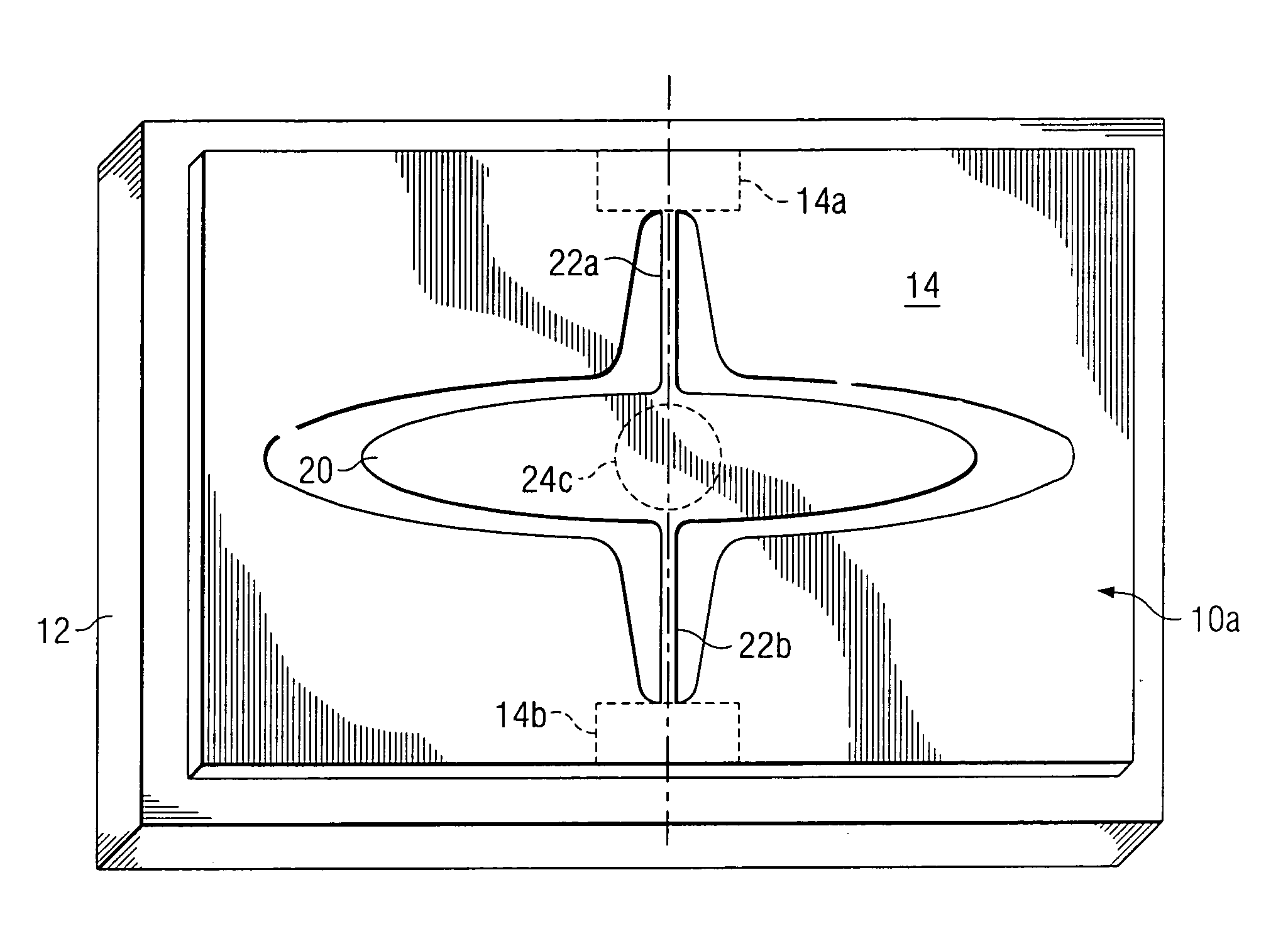
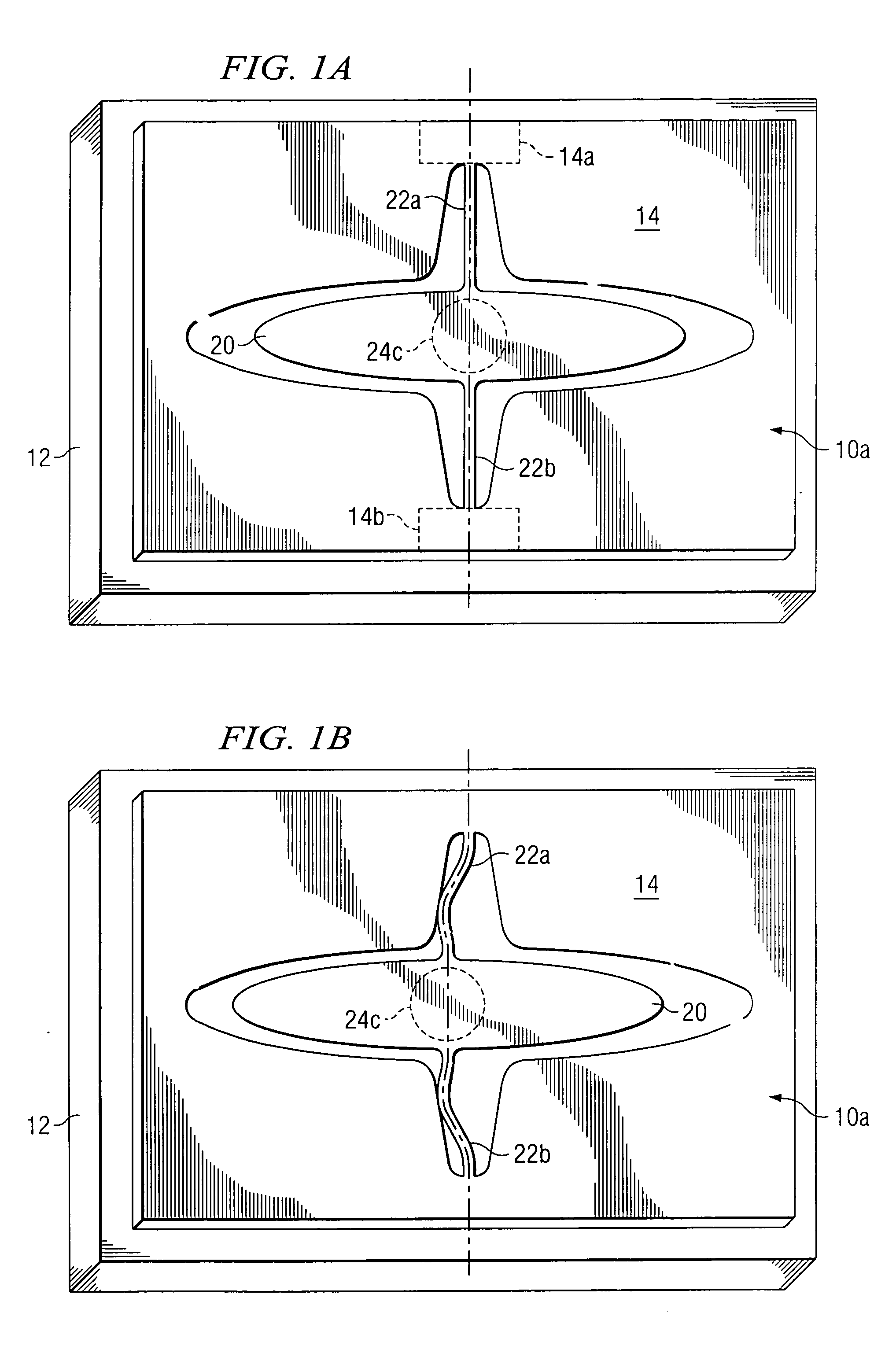
[0014] Referring now to prior art FIGS. 3A and 3B, there is shown a dual axis torsional hinged device structure 10 mounted to a substrate 12. It will be appreciated that although the figures illustrate mirror structures, other torsional hinged devices including, but not limited to, diffraction gratings and refractive, reflective and diffractive lens may also benefit from the teachings of the present invention. In the illustrative embodiment, the torsional hinged structure is a MEMS device such as a dual axis mirror having a support frame 14, which is connected to a Gimbals ...


PUM


Abstract

Method and structure for mounting a torsional hinged device, such as a mirror, having a first TCE (thermal coefficient of expansion) on a substrate having a second TCE different than said first TCE. The structure comprising a plurality of compliant support posts between the substrate and the torsional hinged device that deform when the contraction and / or expansion of the torsional hinged device is different than the corresponding contraction and expansion of the substrate.

Description

[0001] This application claims the benefit of U.S. Provisional Application No. 60 / 638,485, filed on Dec. 22, 2004, entitled Method Of Reducing Thermal Stresses On A MEMS Mirror, which application is hereby incorporated herein by reference.TECHNICAL FIELD [0002] The present invention relates to torsionally hinged devices, such as mirrors, and more particularly to reducing thermal stresses on the devices even when mounted to a substrate having a significantly different TCE (thermal coefficient of expansion). BACKGROUND [0003] In recent years, MEMS (Micro Electro Mechanical Systems) torsional hinged mirror structures have found significant application in telecommunication and free space optic systems such as optical switches and fiber optic replacement for broadband communications. Strides have also been made as replacements for spinning polygon mirrors used as the engine for high speed printers and some types of display systems. Such torsional hinged mirror structures have certain adv...

Claims


Application Information

Patent Timeline
IPC IPC(8): G02F1/00
CPCB81B3/0072B81B2201/047B81B2203/0109G02B26/0808G02B26/0866G02B26/0875
Inventor TURNER, ARTHUR MONROEORCUTT, JOHN W.SIMPSON, CARTER BRUCE
Owner TEXAS INSTR INC
Learn More