Laminated electronic card assembly

a technology of electronic cards and laminated parts, applied in the field of electronic cards, to achieve the effect of reasonable cos

Inactive Publication Date: 2013-09-24
PRIVASYS
View PDF213 Cites 30 Cited by
  • Summary
  • Abstract
  • Description
  • Claims
  • Application Information

AI Technical Summary

Benefits of technology

[0009]Accordingly, it is a primary object of the present invention to advance an electronic card assembly that is viable and can be manufactured at a reasonable cost while still meeting the necessary constructs necessary for its use and acceptance.

Problems solved by technology

In view of all of the constraints facing development of a such a suitable electronic card, such a card has not yet been introduced to the market, despite a long felt need for such a card, and ongoing research and development efforts by many different entities.

Method used


Image

  • Laminated electronic card assembly
  • Laminated electronic card assembly
  • Laminated electronic card assembly

Examples


Embodiment Construction

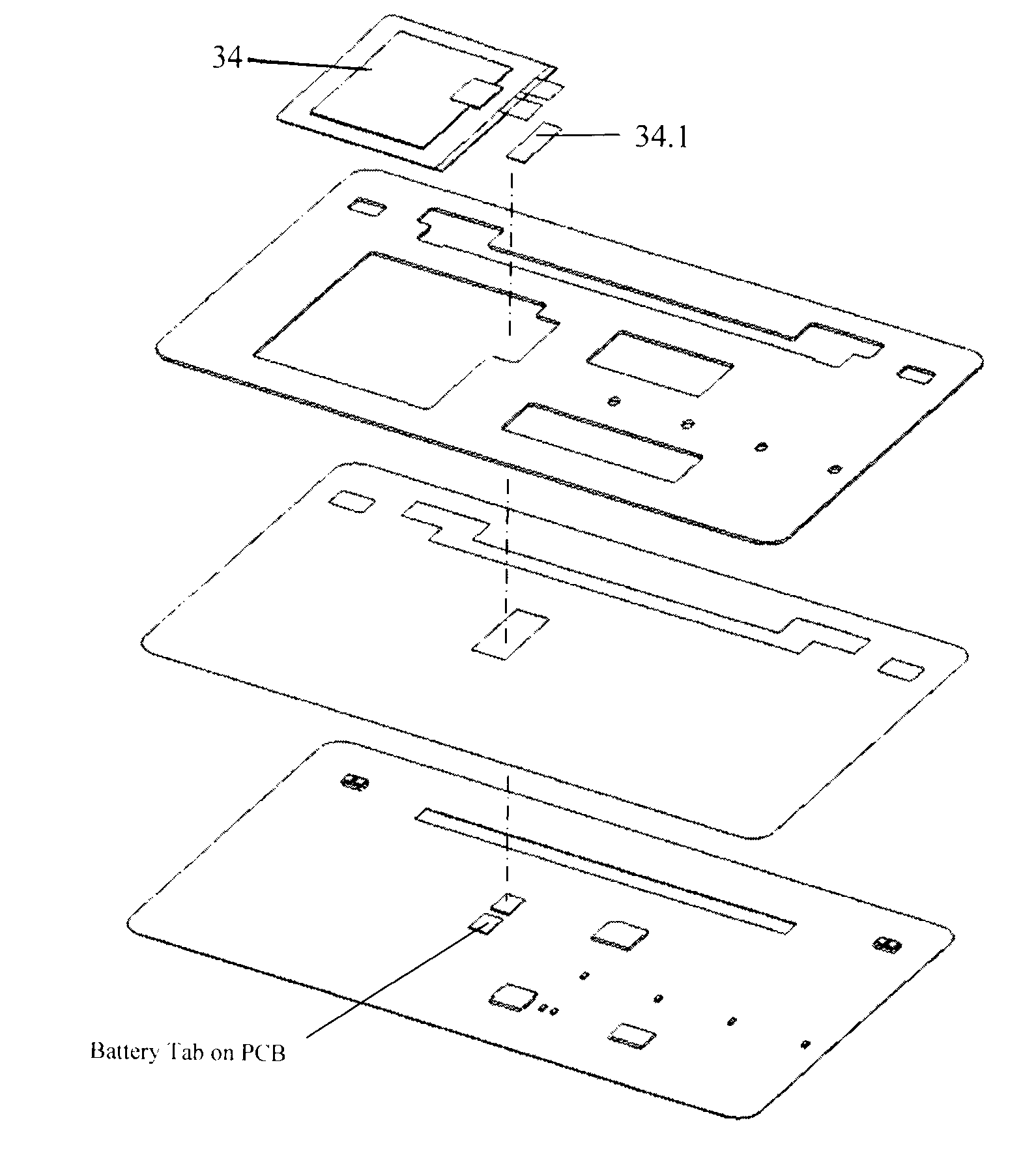
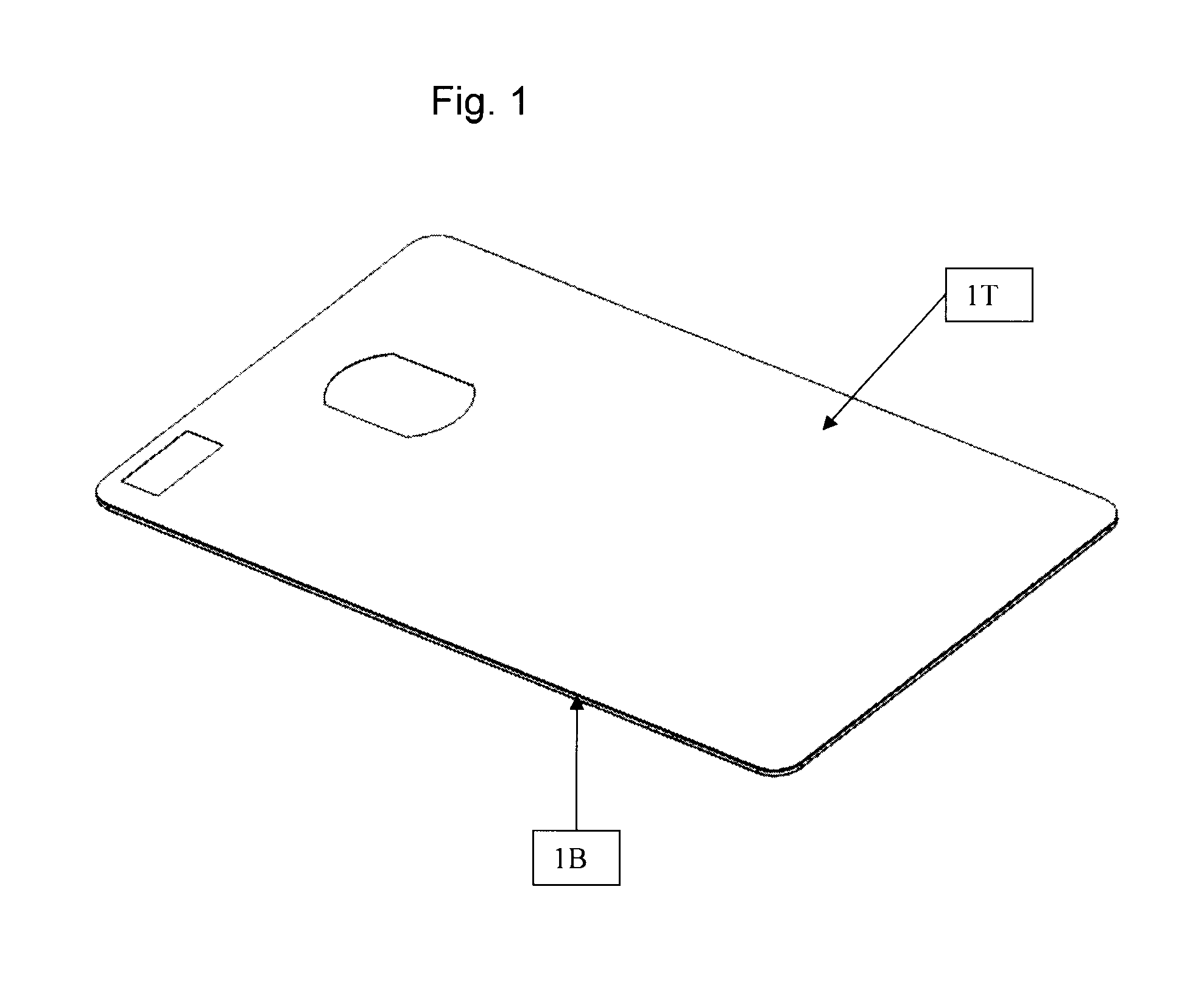
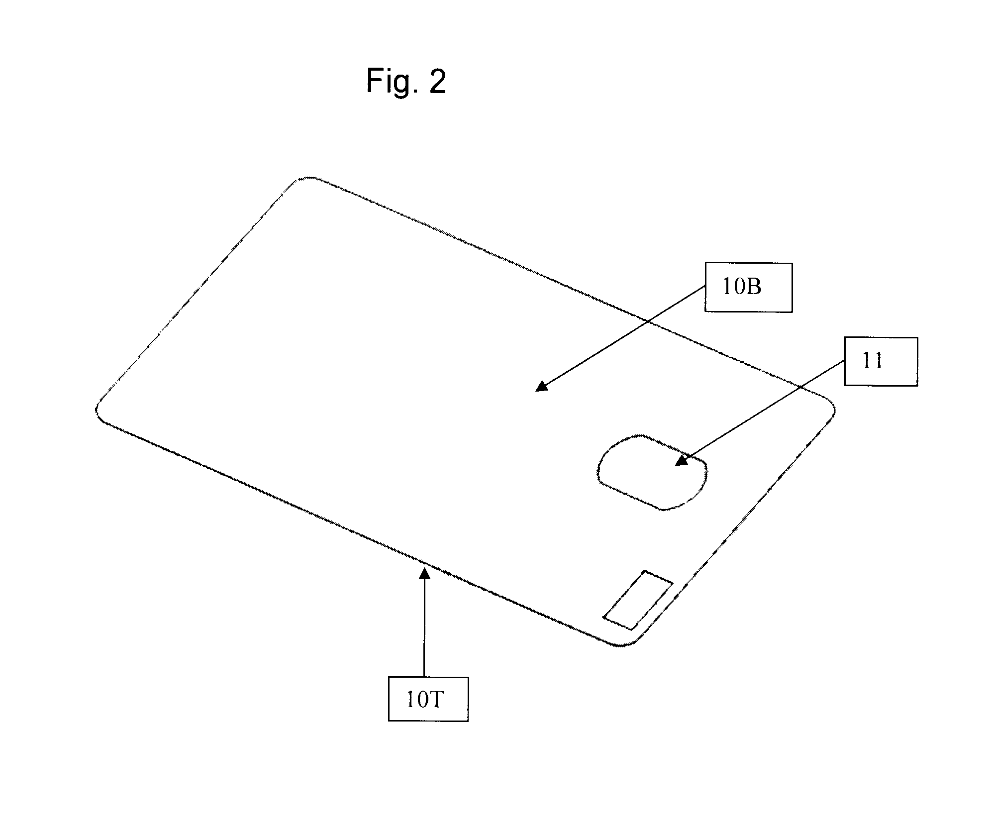
[0014]The present invention is generally directed to a card, such as a debit or credit card, which has the capability of performing electronic functions. For such a card to be widely accepted, it should be able to satisfy the internationally accepted ISO 7816 Standard for Smart Cards, the disclosure of which is specifically incorporated herein by reference. In addition, for such a card to be used as a credit or debit card, it must also be able to satisfy the internationally accepted ISO 7810 standard, the disclosure of which is specifically incorporated herein by reference. These standards, and some of the considerations that go into the various electronic components needed to satisfy these standards, are set forth in greater detail in U.S. Ser. No. 11 / 413,595, filed Apr. 27, 2006, the disclosure of which is specifically incorporated herein by reference.

[0015]The present invention will now be discussed in connection with one or more preferred embodiments shown in the Figures. In the...


PUM

PropertyMeasurementUnit
temperatureaaaaaaaaaa
thicknessaaaaaaaaaa
temperatureaaaaaaaaaa

Abstract

An electronic card is assembled from top and bottom graphic layers, top and bottom thermal sensitive adhesion tapes and an inlay assembly laminated together. The inlay assembly is made of a sub-assembly of a PCB base with one or more electronic components mounted to it, thermal sensitive adhesion tape and a stiffening substrate, all laminated together, while a battery insert and possible additional inserts made of PVC are mounted in openings in the sub-assembly around electronic components such as the battery. The stiffening substrate has a thermal coefficient substantially the same as that of the PCB base. The card need not contain any solder connections and is ISO 7810 compliant. Lamination is performed at a warm, not hot, temperature that does not damage the battery or melt any components together.

Description

CROSS-REFERENCE TO RELATED APPLICATIONS[0001]The present application is a continuation of U.S. patent application Ser. No. 12 / 892,759, filed Sep. 28, 2010, the disclosure of which is specifically incorporated herein by reference. The present application is also a continuation-in-part of U.S. patent application Ser. No. 13 / 102,991, filed May 6, 2011, which is a continuation of U.S. Ser. No. 12 / 726,868, now issued as U.S. Pat. No. 7,954,724, which was a continuation application of U.S. Ser. No. 11 / 413,595, filed Apr. 27, 2006, which was a continuation-in-part application of U.S. Ser. No. 11 / 391,719, filed Mar. 27, 2006 and which also claimed the priority benefit of U.S. Ser. No. 60 / 675,388, filed Apr. 27, 2005, all of which are specifically incorporated herein by reference.FIELD OF THE PRESENT INVENTION[0002]The present invention is in the field of electronic cards.BACKGROUND OF THE INVENTION[0003]The credit and debit card industry issues billions of cards. In the United States, most ...

Claims


Application Information

Patent Timeline
Patent Type & Authority Patents(United States)
IPC IPC(8): G06K19/02
CPCG06F21/77G06F21/81G06Q20/341G06Q20/40975G07F7/1008G07F7/1016G06F7/02G06K17/00G06K19/073G06K19/077
Inventor FOO, ERICZIEGLER, JOANPOIDOMANI, MARKROUTHENSTEIN, LAWRENCEALON, ZIVMCGUIRE, CHARLES
Owner PRIVASYS
Why Eureka
Try Eureka