Sonar

a technology of sonar and resonant, applied in the field of sonar, can solve the problem that the information cannot be accurately extracted under water, and achieve the effect of reducing the transient response tim

Active Publication Date: 2006-06-22
FURUNO ELECTRIC CO LTD
View PDF3 Cites 19 Cited by
  • Summary
  • Abstract
  • Description
  • Claims
  • Application Information

AI Technical Summary

Benefits of technology

[0018] In the invention, in extracting only the echo signal, constancy of the tailing signal (meaning that an amplitude and a phase of the tailing signal do not change very time the tailing signal is transmitted) is required to be guaranteed. This is on the premise that the transmission signal is constant. Thus, in the embodiment of the invention, when a transmission condition for the transmission signal changes, a past sampling value is initialized. Initialization means replacement of the past sampling value with a first sampling value after the change of the transmission condition. This makes it possible to minimize a transient response time. The transmission condition changes, for example, when a transmission pulse width changes or a transmission output changes according to switching of a detection range or when a transmission waveform changes because a modulation system is switched.
[0019] In the case of a sonar having a beam stabilize function for automatically adjusting a directional pattern of a beam by controlling a phase of a transmission signal according to swing of a hull, a waveform of the transmission signal changes every time according to the swing of the hull. In the embodiment of the invention, past sampling values used in the low-pass filter or the high-pass filter are accumulated in association with swing angles of the hull and, when the hull swings, a tailing signal is removed and only an echo signal is extracted on the basis of sampling values corresponding to the swing angles. This makes it possible to remove the tailing signal and surely extract only the echo signal even if the hull swings.

Problems solved by technology

As described above, in the conventional sonar, a shoal of fish and the like near the water surface are not clearly displayed and underwater information cannot be accurately extracted because of a tailing signal caused immediately after transmission of an ultrasonic wave.

Method used


Image

  • Sonar
  • Sonar
  • Sonar

Examples


Embodiment Construction

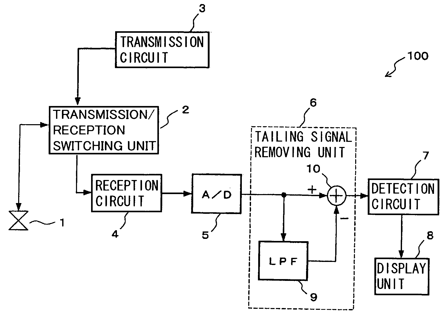
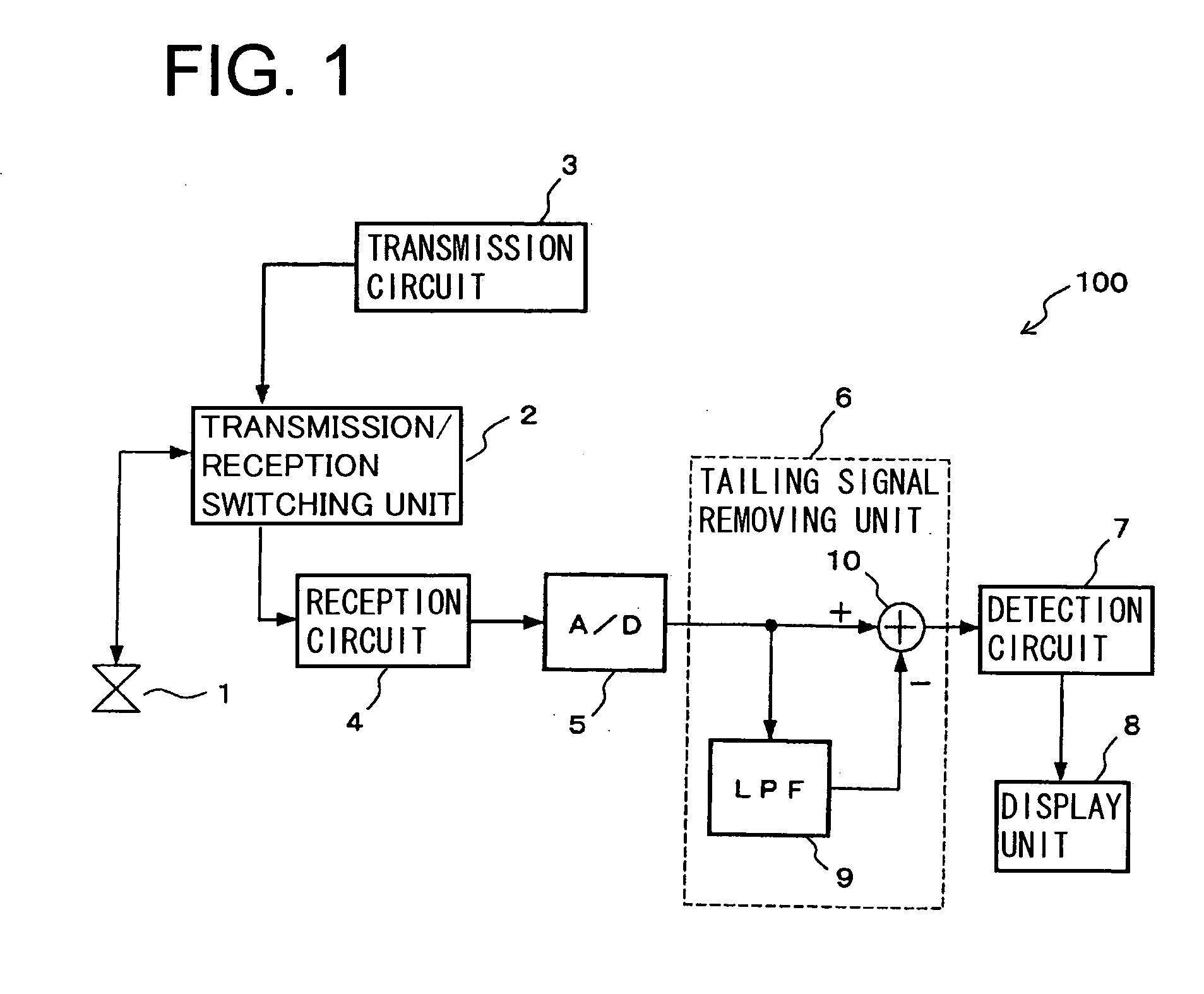
[0029]FIG. 1 is a block diagram of a fish finder 100 that is an embodiment of a sonar according to the invention. Reference numeral 1 denotes a transducer that emits an ultrasonic wave into the water and receives an echo reflected in the water and converts the echo into an electric signal; 2, a transmission / reception switching unit that switches an operation of the transducer 1 to transmission and reception; 3, a transmission circuit that outputs a transmission signal of a predetermined frequency to the transducer 1; and 4, a reception circuit that receives the electric signal converted by the transducer 1 and extracts a reception signal in a predetermined frequency band. Reference numeral 5 denotes an A / D converter that samples the reception signal extracted by the reception circuit 4 at a fixed time interval and converts the reception signal into a digital signal; 6, a tailing signal removing unit that removes a tailing signal included in the reception signal subjected to digital ...


PUM


Abstract

A sonar emits an ultrasonic wave into the water from a transducer on the basis of a transmission signal outputted from a transmission circuit, receives an echo reflected in the water with the transducer and converts the echo into an electric signal, and displays underwater information on a display unit on the basis of an echo signal extracted by processing the electric signal. A tailing signal removing unit for removing a tailing signal and extracting only the echo signal is provided in the sonar such that a video of a surface layer fish shoal is clearly displayed on a screen of the display unit without being hidden by a video of the tailing signal.

Description

BACKGROUND OF THE INVENTION [0001] 1. Field of the Invention [0002] The present invention relates to sonars using ultrasonic waves such as a fish finer and an echo sounder that are mounted on a ship. [0003] 2. Description of the Related Art [0004] A sonar is an ultrasonic apparatus that emits an ultrasonic wave from a transducer attached to a hull into the water, receives echoes of the ultrasonic wave reflected on a shoal of fish, a water bottom, and the like and returned to the sonar, and displays underwater information. For example, in the case of a fish finder, echoes from the water are distinguished by colors according to signal intensities and displayed on a display unit. As an example, strong echoes returned from a shoal of fish and a water bottom with large reflection intensities are displayed in reddish brown and a weak echo returned from a shoal of fish with a small reflection intensity is displayed in blue, green, or the like. [0005] In such a sonar, since one transducer p...

Claims


Application Information

Patent Timeline
Patent Type & Authority Applications(United States)
IPC IPC(8): G01S15/00
CPCG01S7/527G01S15/96Y10S367/901
Inventor ISHIHARA, SHINJISATOH, TAKANORIINOUCHI, MITSUHIROKUBOTA, OSAMUONISHI, YURIKO
Owner FURUNO ELECTRIC CO LTD
Why Eureka
Try Eureka