
Packet reorder resolution in a load-balanced network architecture

Inactive Publication Date: 2006-06-22
ALCATEL-LUCENT USA INC
View PDF4 Cites 36 Cited by
  • Summary
  • Abstract
  • Description
  • Claims
  • Application Information

AI Technical Summary

Benefits of technology

[0013] The present invention meets the above-noted need by providing techniques which substantially eliminate or otherwise limit the amount of packet reordering that is required in a given load-balanced network architecture.

Problems solved by technology

Although such networks are advantageous in that they incorporate substantial reliability and protection mechanisms, their primary disadvantage has been a lack of bandwidth efficiency.
Since data traffic is inherently bursty, it leads to underutilization of the fixed-bandwidth connections of conventional circuit-switched networks.
Despite the improvements associated with the recently-developed VC and LCAS protocols, there remain problems in both circuit-switched and packet-switched network architectures.
Generally, existing architectures can be difficult to scale so as to accommodate large mesh topologies, and can still suffer from bandwidth efficiency or switching complexity concerns.
For example, an architecture comprising an IP overlay over SONET may require an excessive amount of link bandwidth, while a pure IP network architecture will typically require a large amount of packet switching capacity at each network node.
An important issue that may arise in the context of load-balanced architectures such as that described in the above-cited U.S. patent application Ser. No. 10 / 785,352 relates to packet reordering.
However, these techniques exhibit a number of drawbacks, particularly in the load-balanced network architecture context described above.
However, this approach fails to account for path delay variations, and is thus not readily applicable to a geographically-distributed network.

Method used


Image

  • Packet reorder resolution in a load-balanced network architecture
  • Packet reorder resolution in a load-balanced network architecture
  • Packet reorder resolution in a load-balanced network architecture

Examples


Embodiment Construction

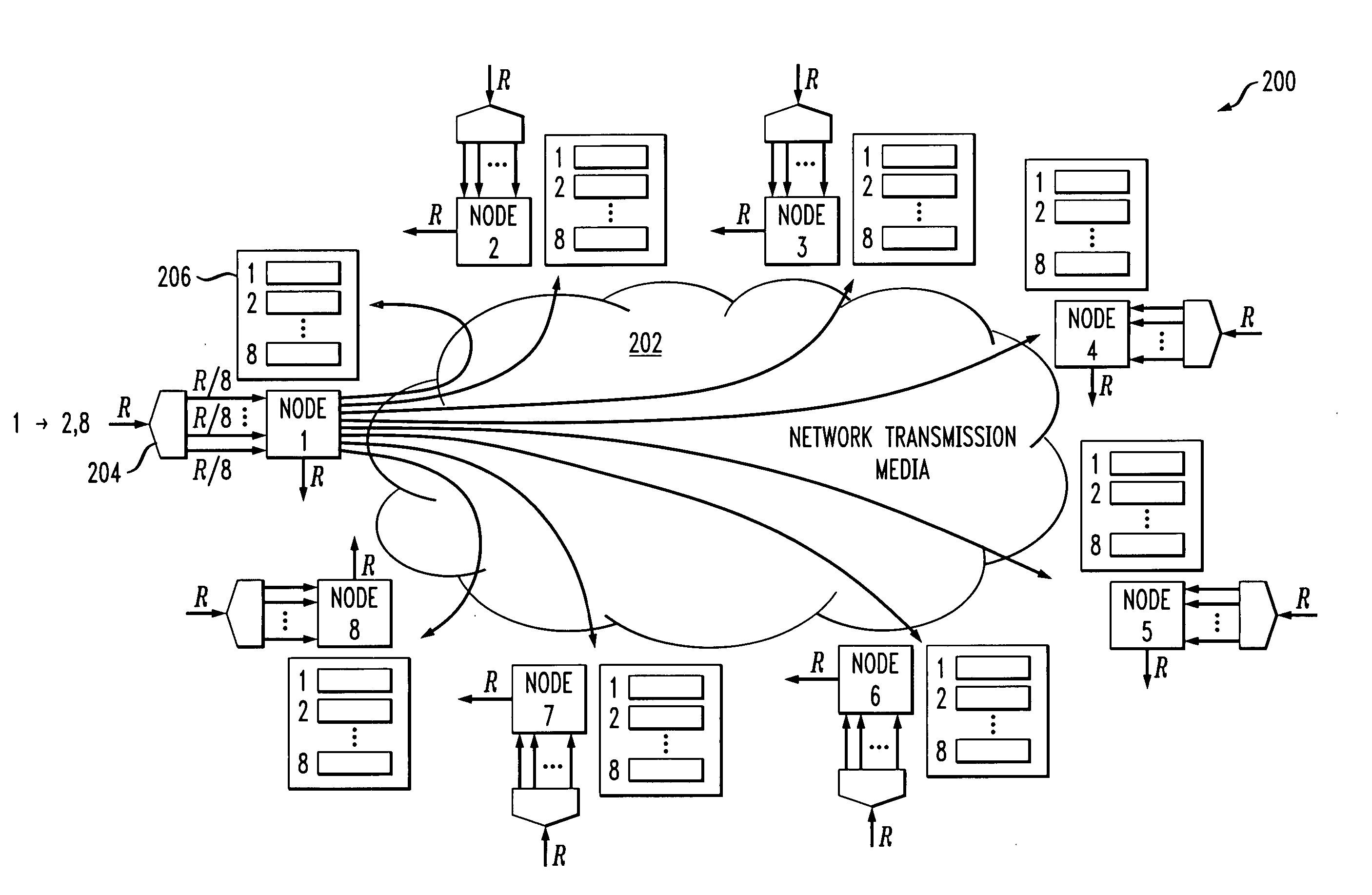
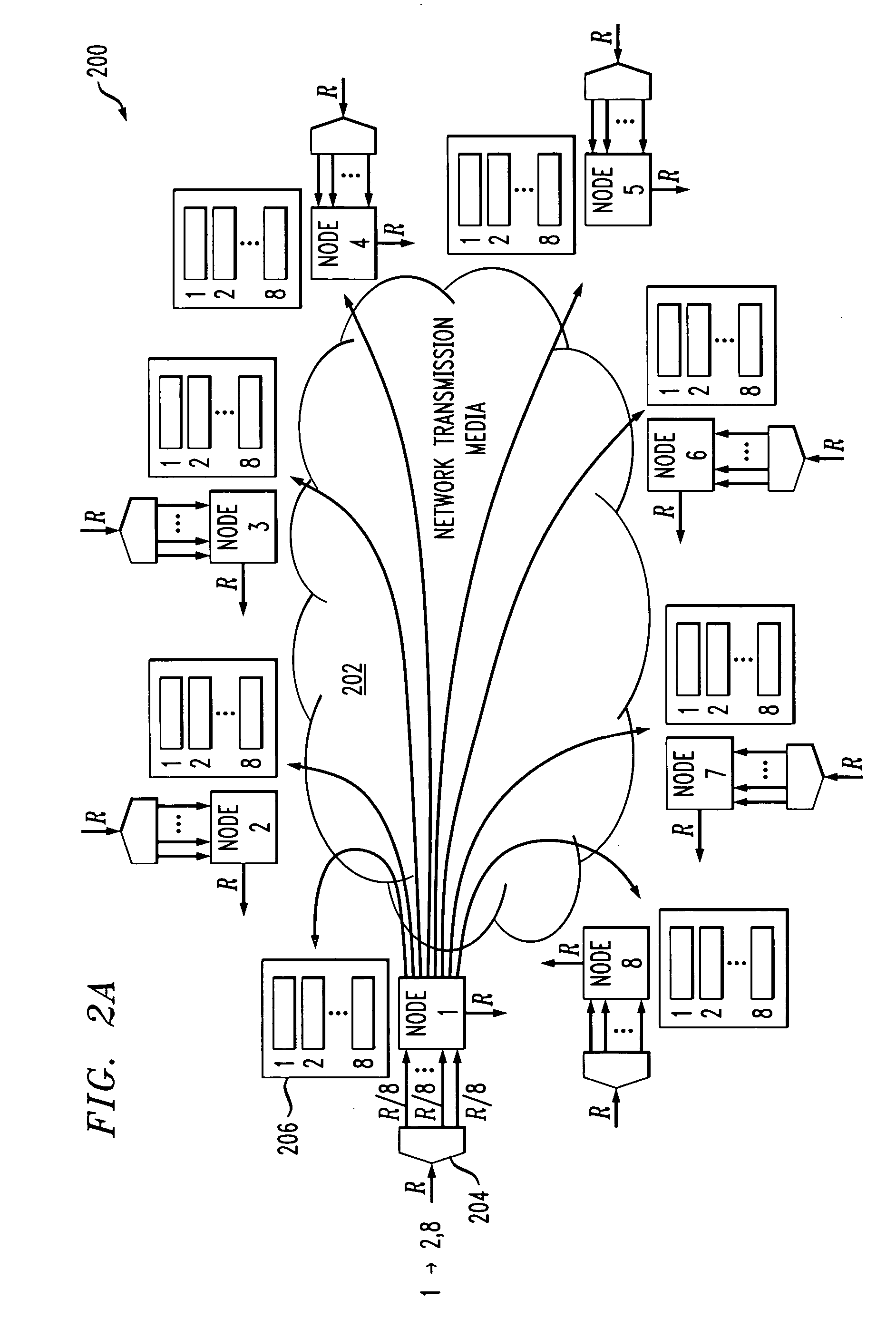
[0023] The invention will be illustrated herein in conjunction with an illustrative embodiment which utilizes a load-balanced network architecture of the type described in the above-cited U.S. patent Ser. No. 10 / 785,352. It is to be appreciated, however, that the invention is not limited to the particular network architecture and associated load balancing process of the illustrative embodiment, but is more generally applicable to any network application in which it is desired to provide improved packet reordering.

[0024] For example, although well suited for use with EoS data traffic, with or without virtual concatenation, the invention can be used with any type of traffic flow.

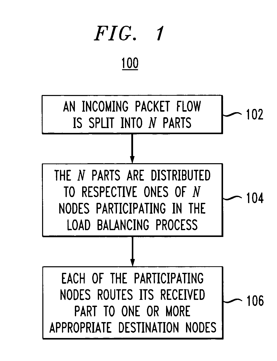
[0025] Referring now to the flow diagram of FIG. 1, a load balancing process in an illustrative embodiment of the invention will be described. The process in this example includes steps 102, 104 and 106. It will be assumed for purposes of simplicity and clarity of illustration that the network comprises N no...


PUM


Abstract

A load-balanced network architecture is disclosed in which a traffic flow deliverable from a source node to a destination node via intermediate nodes is split into parts, and the parts are distributed to respective ones of the intermediate nodes. Path delay differences for the parts are substantially equalized by delay adjustment at one or more of the intermediate nodes, and packets of one or more of the parts are scheduled for routing from respective ones of the intermediate nodes to the destination node based on arrival times of the packets at the source node.

Description

RELATED APPLICATION [0001] The subject matter of the present application is related to that of U.S. patent application Ser. No. 10 / 785,352, filed Feb. 24, 2004 in the name of inventors Harsha S. Nagesh et al. and entitled “Load Balancing Method and Apparatus for Ethernet Over SONET and Other Types of Networks,” which is incorporated by reference herein.FIELD OF THE INVENTION [0002] The present invention relates generally to the field of data communication networks, and more particularly to load balancing techniques for use in such networks. BACKGROUND OF THE INVENTION [0003] Circuit-switched network architectures, such as those based on synchronous optical network (SONET) or synchronous digital hierarchy (SDH) standards, were originally designed to support voice traffic using dedicated fixed-bandwidth connections. Although such networks are advantageous in that they incorporate substantial reliability and protection mechanisms, their primary disadvantage has been a lack of bandwidth...

Claims


Application Information

Patent Timeline
IPC IPC(8): H04J3/06H04J3/04H04L12/56H04L12/28
CPCH04J3/1617H04J2203/0083H04J2203/0094H04L47/10H04L47/125H04L47/283H04L47/34
Inventor NAGESH, HARSHA S.POOSALA, VISWANATHSENGUPTA, SUDIPTAWINZER, PETER J.
Owner ALCATEL-LUCENT USA INC
Learn More