Machine tool

a technology of machine tools and tools, applied in the field of machine tools, can solve the problems of affecting the assembling accuracy of the assembling device, the inability of the cover device to cope with the case, and the influence of various sensors and limit switches, so as to ensure the preventing of coolant and chip, the effect of high air tightness and enhanced assembling accuracy

Inactive Publication Date: 2006-06-22
KOMATSU NTC LTD
View PDF12 Cites 25 Cited by
  • Summary
  • Abstract
  • Description
  • Claims
  • Application Information

AI Technical Summary

Benefits of technology

[0020] In the invention as set forth in the first aspect, it is possible in a machine tool of a type, in which a machining unit is advanced in a Z-axis direction at the time of machining of a work, to prevent coolant and chip from entering into a machining region during machining of a work. Also, it is possible to surely prevent coolant and chip from being taken into a machine region due to retreating of the machining unit.
[0021] In the invention as set forth in the second aspect, when a machining head is to be exchanged by one having a different body size, such exchange can be met by exchange of a seal frame.
[0022] In the invention as set forth in the third aspect, when a machining head is to be exchanged by one having a different body size, such exchange can be met by exchange of a head cover.
[0023] In the invention as set forth in the fourth or fifth aspect, it is possible in a machine tool, in which a machining head can be moved in a X-axis direction (laterally) or a Y-axis direction (vertically), to prevent coolant and chip from entering into a side of a machining unit during machining of a work.
[0024] In the invention as set forth in the sixth aspect, it is possible to simply construct an extensible cover of high air tightness.
[0025] In the invention as set forth in the seventh aspect, the construction of assembling a machining unit to a bed is made simple to enhance an assembling accuracy and to enhance accuracy, with which tools machine a work.

Problems solved by technology

When such coolant and chip enter into a machine region on a side of the machining unit from the machining head, a harmful influence is exerted on various sensors and limit switches provided on the machining unit, or slide members, seal members, or the like on X-axis, Y-axis, and Z-axis drive mechanisms.
Since the conventional cover device, disclosed in JP-UM-A-4-115554, for machine tools is not constructed such that a movable cover is brought into close contact with the opening window of the compartment cover during machining of a work, however, there are caused problems that sealing is made incomplete, and a part of coolant enters into a machine region on a side of the machining unit because the movable cover is opened downward.
Further, the cover device cannot cope with the case where a machining unit is of a type, in which tools are driven left and right, and up and down.

Method used


Image

  • Machine tool
  • Machine tool
  • Machine tool

Examples


first embodiment

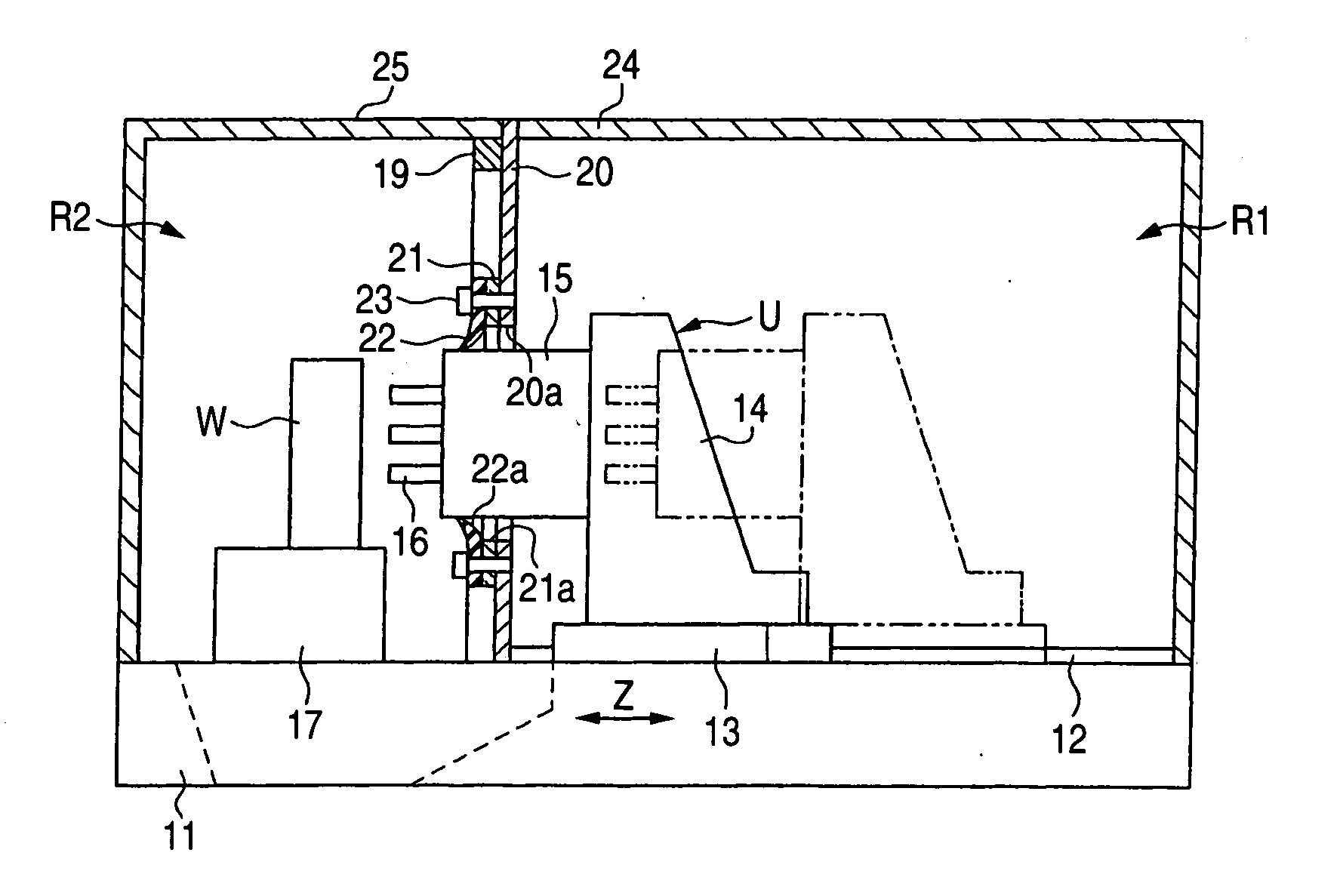
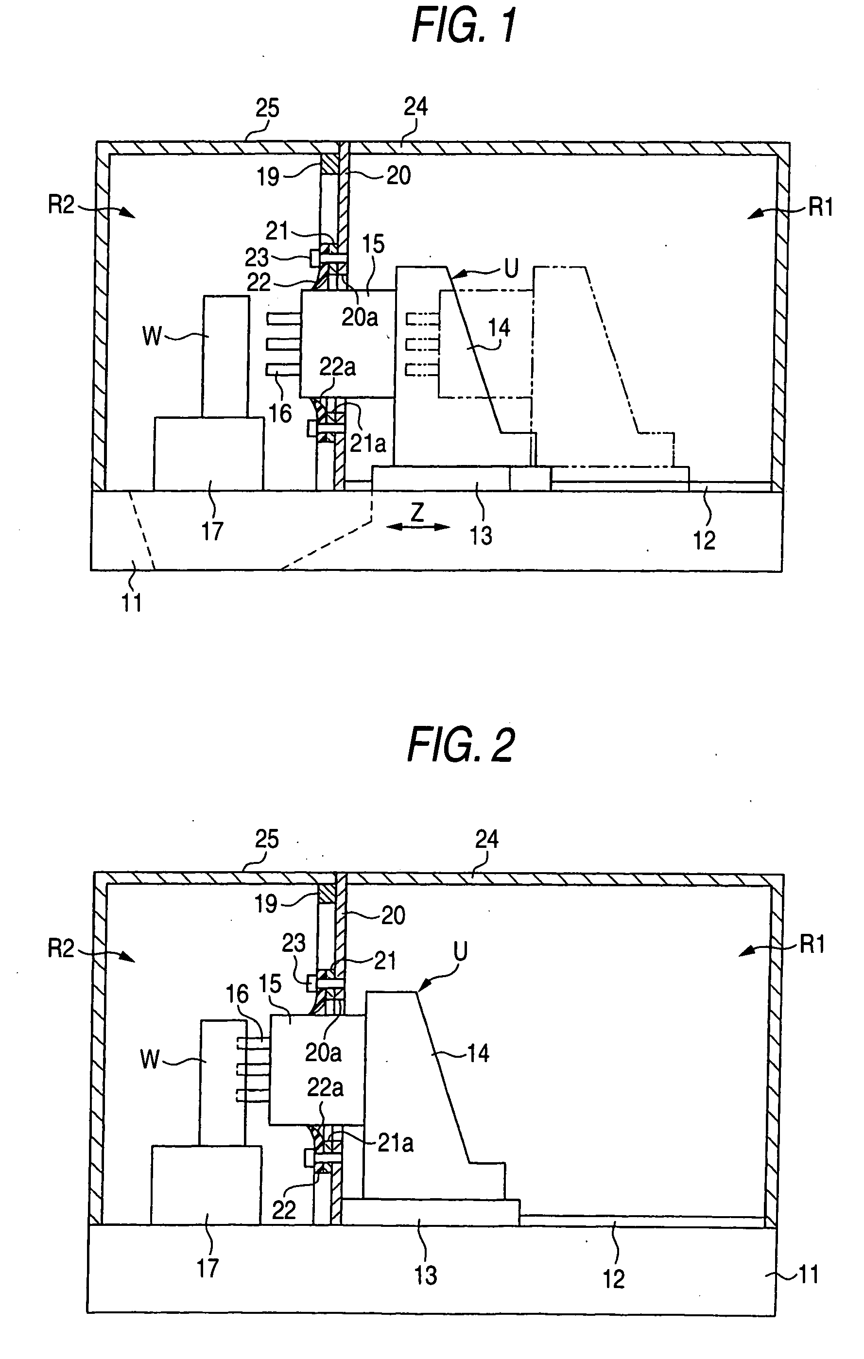
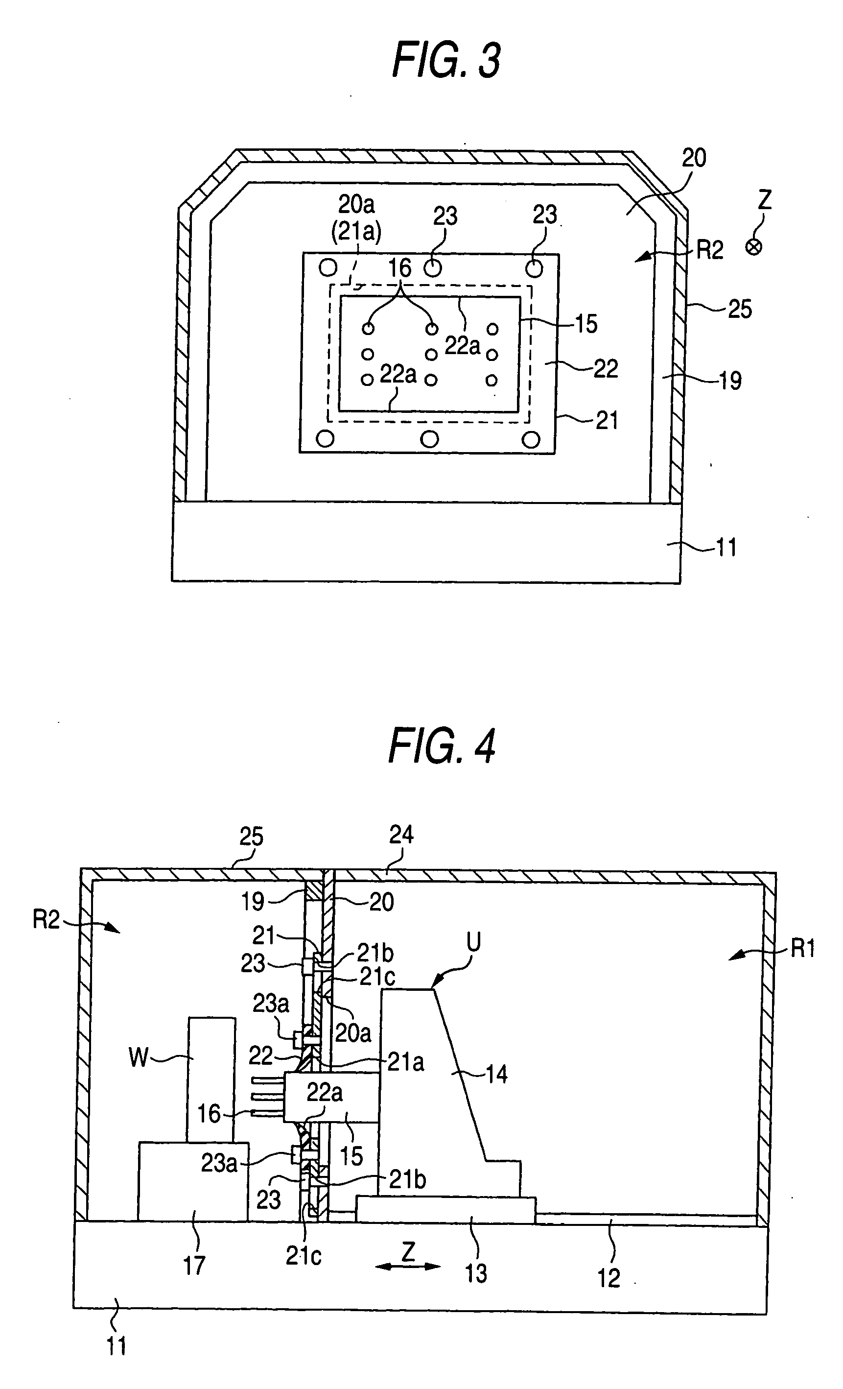
[0040] A first embodiment, in which a cover device for machine tools, according to the invention is embodied, is described below with reference to FIGS. 1 to 3.

[0041] As shown in FIG. 1, Z-axis guide rails 12 are laid immediately on an upper surface of a bed 11 in a Z-axis direction (front and back), and a Z-axis saddle 13 reciprocated in the Z-axis direction by a Z-axis drive mechanism including a servomotor (not shown) is mounted on the Z-axis guide rails 12. A column 14 is mounted on an upper surface of the Z-axis saddle 13 to be moved in the Z-axis direction. A machining head 15 is mounted on a front surface (left side in FIG. 1) of the column 14 to be directed in the Z-axis direction, and a plurality of drills 16 as tools are mounted on the machining head 15 to constitute a multi spindle head. And the drills 16 are rotatingly driven by a rotary mechanism (not shown) provided in the machining head 15.

[0042] In this embodiment, a machining unit U is composed of the Z-axis saddl...

second embodiment

[0067] Subsequently, a second embodiment of the invention is described with reference to FIGS. 8 to 10. In addition, those members in second and third embodiments, which have the same function as that in the first embodiment, are denoted by the same reference characters and an explanation thereof is omitted.

[0068] In the second embodiment, as shown in FIG. 8, Y-axis guide rails 31 directed in a Y-axis direction (vertical) is provided on the front surface of the column 14, and a Y-axis saddle 32 is mounted on the Y-axis guide rails 31 such that it can be reciprocated vertically by a Y-axis drive mechanism (not shown) including a servomotor. The machining head 15 is mounted on a front surface of the Y-axis saddle 32. A roll cover mechanism 33 is mounted on the Z-axis saddle 13 and the column 14 to serve as a shield cover to allow up-and-down movements of the machining head 15 and to protect the outer peripheral surface of the body of the machining head 15, the Y-axis guide rails 31, ...

third embodiment

[0076] Subsequently, a third embodiment of the invention is described with reference to FIGS. 11 and 12.

[0077] In the third embodiment, a X-axis saddle 73 is mounted on X-axis guide rails 72, which are laid on the upper surface of the Z-axis saddle 13 as shown in FIG. 11 to be in parallel to each other in a X-axis direction (direction perpendicular to a plane of the drawing), such that it can be reciprocated in the X-axis direction, and the column 14 is mounted on an upper surface of the X-axis saddle 73. Also, a roll cover mechanism 33 provided with the same cover sheet 41 as that of the roll cover mechanism 33 is laterally mounted on the support frame 19. Guide members 75 are mounted longitudinally in two locations on the sides of the column 14 to guide a base end portion of a guide bar 74 in the Z-axis direction. A front end portion of the guide bar 74 is bent upward into a L-shape, and a tip end of the front end portion is connected through connection plates 76 to a corner port...


PUM

PropertyMeasurementUnit
sizesaaaaaaaaaa
sizeaaaaaaaaaa
corrosion-resistantaaaaaaaaaa

Abstract

A machine tool has a support table provided on an upper surface of a bed to support a work, a Z-axis saddle, a machining unit mounted on the Z-axis saddle and provided with a machining head, a compartment cover arranged on the bed to compartment a region and a machine region, an opening window provided on the compartment cover to permit the machining head to go in and out therethrough, and a seal member in the form of a closed ring to be mounted on an inner peripheral edge of the opening window of the compartment cover, wherein an entire periphery of an outer peripheral surface of the machining head is brought into sliding contact with an inner peripheral edge of the seal member in a state, in which the machining head is moved into the machining region from a tool exchange position within the machine region.

Description

BACKGROUND OF THE INVENTION [0001] 1. Field of the Invention [0002] The present invention relates to a machine tool for advancing and retreating a machining unit from a work supported on a work support table to perform machining of a work, and more particular, to a cover construction. [0003] 2. Description of the Related Art [0004] Generally, a machine tool comprises a work support table for supporting a work being machined, and a machining unit capable of mounting and dismounting of tools, which perform machining, such as drilling or the like, of the work. The machining unit is composed of a Z-axis saddle mounted on a bet to be able to reciprocate in a Z-axis direction (longitudinally), a column mounted on the Z-axis saddle, and a machining head mounted on the column to grasp tools. And the machining unit is advanced to perform machining of a work, and when machining is terminated, the machining unit is retreated. Also, the column is mounted on the Z-axis saddle to be able to recip...

Claims


Application Information

Patent Timeline
Patent Type & Authority Applications(United States)
IPC IPC(8): B23D77/00B23Q11/08B23B39/16
CPCB23B39/161B23Q11/08B23Q11/085Y10T483/115Y10T408/89Y10T408/98Y10T409/30392Y10S29/059
Inventor SHIRAISHI, YOSHIHIROSUGIHARA, TSUTOMUNUKUI, MITSURU
Owner KOMATSU NTC LTD
Why Eureka
Try Eureka