Coaxial injector screw providing improved small shot metering

a technology of injection screw and small shot metering, which is applied in the field of injection molding, can solve the problems of limited diameter of injection screw, difficult manufacturing of small injection screw, and difficult small injection screw size, and achieve the effect of reducing the cross section area of the screw, high accuracy and reduced movement of the screw

Inactive Publication Date: 2006-06-22
MGS MFG GROUP
View PDF61 Cites 12 Cited by
  • Summary
  • Abstract
  • Description
  • Claims
  • Application Information

AI Technical Summary

Benefits of technology

[0008] The present invention provides an injector screw having a coaxial piston that may be moved independently of the screw. The piston allows an effective variation in the cross section area of the screw allowing the injection shot to be controlled by (1) movement of the piston, (2) reduced movement of the screw alone, or (3) a combination of screw and piston motion. As a result, larger screw diameters may be fabricated and used with actuators having long strokes and high accuracy while still metering small amounts of plastic.
[0010] Thus, it is one object of at least one embodiment of the invention to provide independent control of the effective cross-sectional area of the screw allowing large screw diameters to be used for metering small shots of plastic.
[0012] Thus it is another object of at least one embodiment of the invention to provide simple construction of the screw and of the piston actuating mechanism.
[0015] The screw may be used in an injection-molding machine having an injector barrel with a bore extending along an axis and terminating at a nozzle to abut a mold held by the injection-molding machine. A first actuator may be provided for rotating the screw about the axis, and the second actuator may provide relative movement between the piston and the screw.
[0018] Thus it is another object of at least one embodiment of the invention to provide a simple method of providing a range of small shot sizes by changing the diameter of the piston.
[0020] Thus it is another object of at least one embodiment of the invention to provide an extremely simple method of adapting current injection molding machines to small shot sizes, for example, by using the normal screw actuation mechanisms with a stationary piston that may subtract from the effective area of the screw.

Problems solved by technology

This is difficult for small shot sizes where very little screw movement occurs.
Small injection screws are difficult to manufacture, and there are practical limits on injection screw diameter resulting from the need for thread depth and sufficient root diameter to withstand the torque and compression placed on the injection screw.

Method used


Image

  • Coaxial injector screw providing improved small shot metering
  • Coaxial injector screw providing improved small shot metering

Examples


Embodiment Construction

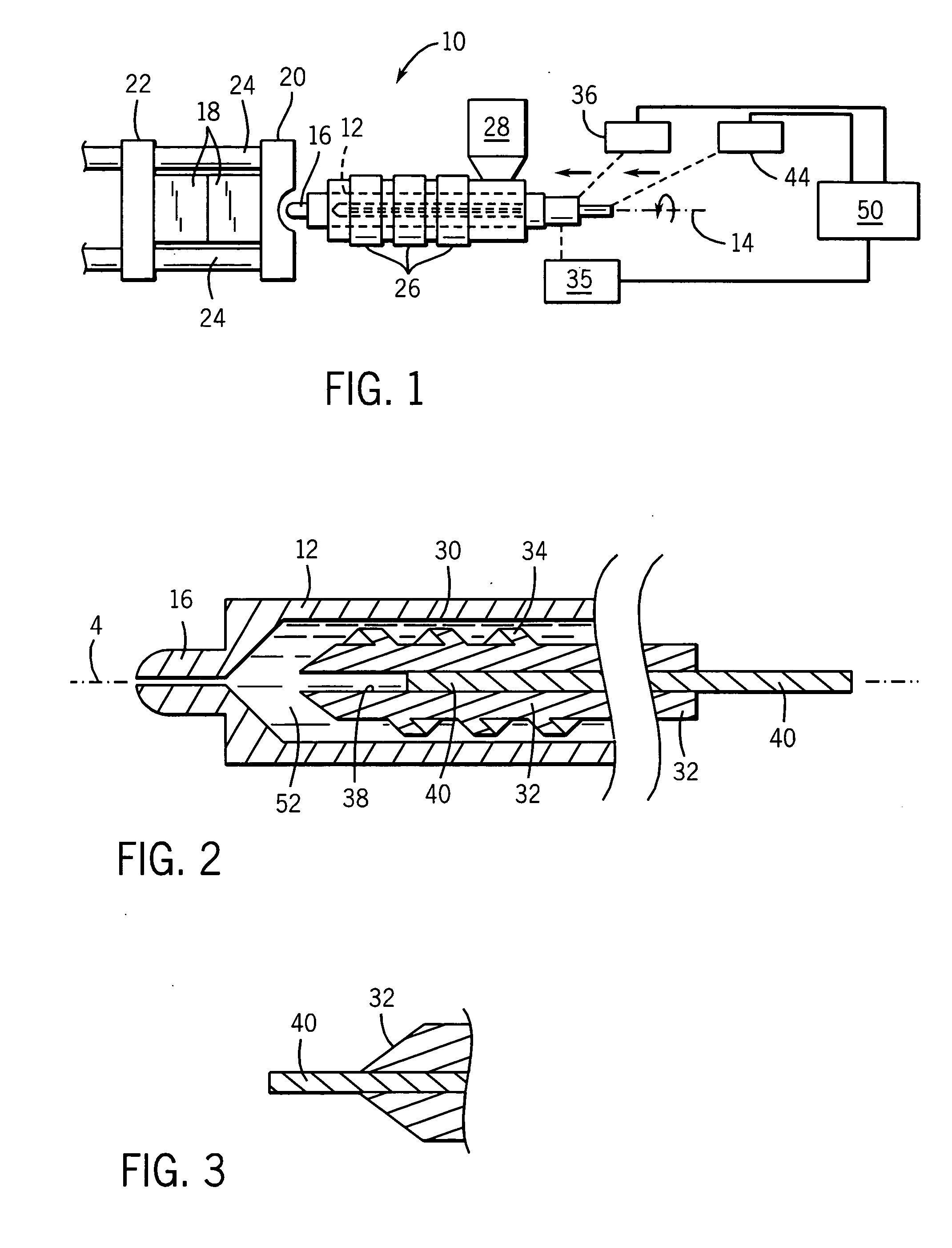
[0029] Referring now to FIG. 1, an injection-molding machine 10 suitable for use with the present invention provides an injector barrel 12 extending along a longitudinal axis 14 having a nozzle 16 defining a front of the injector barrel 12. As is generally understood in the art, one or more heater bands 26 may be placed about the barrel 12 and a rear of the barrel may support a vertically extending hopper 28 providing a source of thermoplastic pellets.

[0030] The nozzle 16 of the injector barrels 12 may abut a mold portion 18 to inject a shot of plastic into a mold formed by the mold portions 18. During the injection process, the mold portions 18 are held clamped together between a stationary platen 20 and a movable platen 22, the latter sliding axially along tie bars 24.

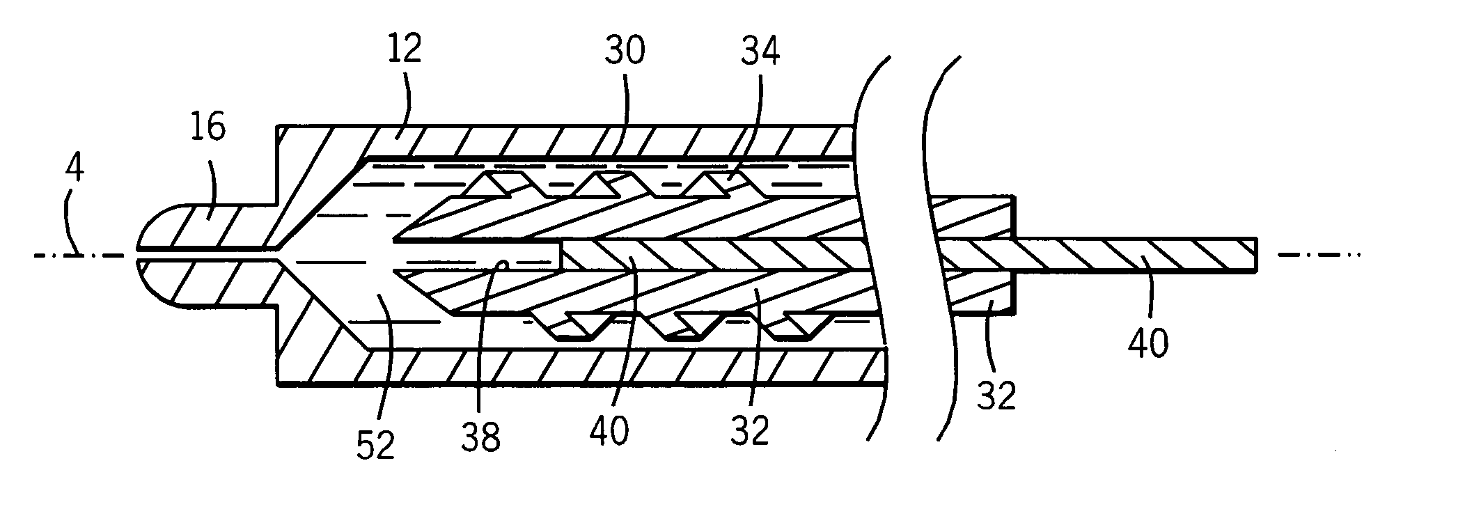
[0031] Referring also to FIG. 2, the barrel 12 may include a central cylindrical bore 30 that may receive an injector screw 32. The injector screw 32 extends generally along axis 14 and has screw threads 34 extendi...


PUM

PropertyMeasurementUnit
axial lengthaaaaaaaaaa
pressureaaaaaaaaaa
timeaaaaaaaaaa

Abstract

A screw for injection molding provides a coaxial piston that allows the effective cross-sectional area of the screw to be varied during the injection cycle permitting small shot metering with relatively large diameter injection molding screws.

Description

CROSS-REFERENCE TO RELATED APPLICATIONS [0001]—STATEMENT REGARDING FEDERALLY SPONSORED RESEARCH OR DEVELOPMENT [0002]—BACKGROUND OF THE INVENTION [0003] The present invention relates generally to injection molding, and more particularly, to an injection screw and barrel providing improved control of small shots of plastic during injection molding. [0004] The injection molding process employs an injector that forces a volume of thermoplastic material (a “shot”) under pressure into a mold cavity. A common injector design provides an outer barrel holding an injection screw. Pellets of thermoplastic resin from a hopper enter the barrel at a feed zone and are received by threads (“flights”) on the injection screw. The injection screw rotates within the barrel to shear, blend, and advances the molten plastic toward the front of the barrel near a nozzle that communicates with the mold cavity. [0005] As molten plastic is advanced toward the front of the barrel, the injection screw retracts,...

Claims


Application Information

Patent Timeline
Patent Type & Authority Applications(United States)
IPC IPC(8): B29C45/18
CPCB29C45/541Y10S425/227
Inventor HAHN, JOHN J.
Owner MGS MFG GROUP
Why Eureka
Try Eureka