Handling machine for rails and handling process associated thereto

a technology of rails and handling machines, applied in the direction of metal rolling arrangements, furnace types, light and heating equipment, etc., can solve the problems of high energy consumption, low efficiency, complex rail handling systems, etc., and achieve the effect of avoiding damage to the external surface of the rail and the handlers, facilitating the handling of the rail, and effectively enduring the deflection and its variations

Active Publication Date: 2016-11-22
DANIELI & C OFF MEC SPA
View PDF7 Cites 0 Cited by
  • Summary
  • Abstract
  • Description
  • Claims
  • Application Information

AI Technical Summary

Benefits of technology

[0015]It is the main object of the present invention to implement a handling machine for handling rails, arranged in line and immediately downstream of a rolling plant, which allows both to easily handle the rail for transferring it from the roller table to the thermal treatment zone, and to ensure an optimal clamping of the rail along its longitudinal extension, thus effectively withstanding the deflection and its variations while allowing a longitudinal movement of the rail caused by thermal shrinkage, thus avoiding damages both to the external surface of the rail and to the handlers.

Problems solved by technology

This implies the need to stock the rolled rails and subsequently heat them before proceeding with the thermal quenching treatment, with high energy consumption and low efficiency.
A first drawback of these solutions is the complexity of the rail handling systems which move the rail on the roller table along the thermal treatment plant.
In particular, if an immersion tank is used, cooling is more uniform lengthwise, but in all cases the temperature difference between the base of the hot rail and the cooled head results in the rail deflection or bending.
Therefore, a second drawback of the known solutions is that these variations of longitudinal profile of the rail, more accentuated at the ends, cause the exertion of high vertical forces on the clamps of the rail handlers; these forces could cause the clamps themselves to open and therefore the rail to drop.
The clamps of the prior art have the disadvantage of being unsuitable for withstanding and containing said deflection and its variations during the thermal treatment.
On one hand, these forces ensure a good clamping of the rail while being moved and transferred close to the cooling tank, but on the other hand they hinder the longitudinal movement of the rail caused by thermal shrinkage that the rail itself undergoes when it is cooled down.
This shortening may cause damages both to the rail surface and to the handlers themselves due to the high clamping forces of the clamps on the rail.

Method used


Image

  • Handling machine for rails and handling process associated thereto
  • Handling machine for rails and handling process associated thereto
  • Handling machine for rails and handling process associated thereto

Examples


first embodiment

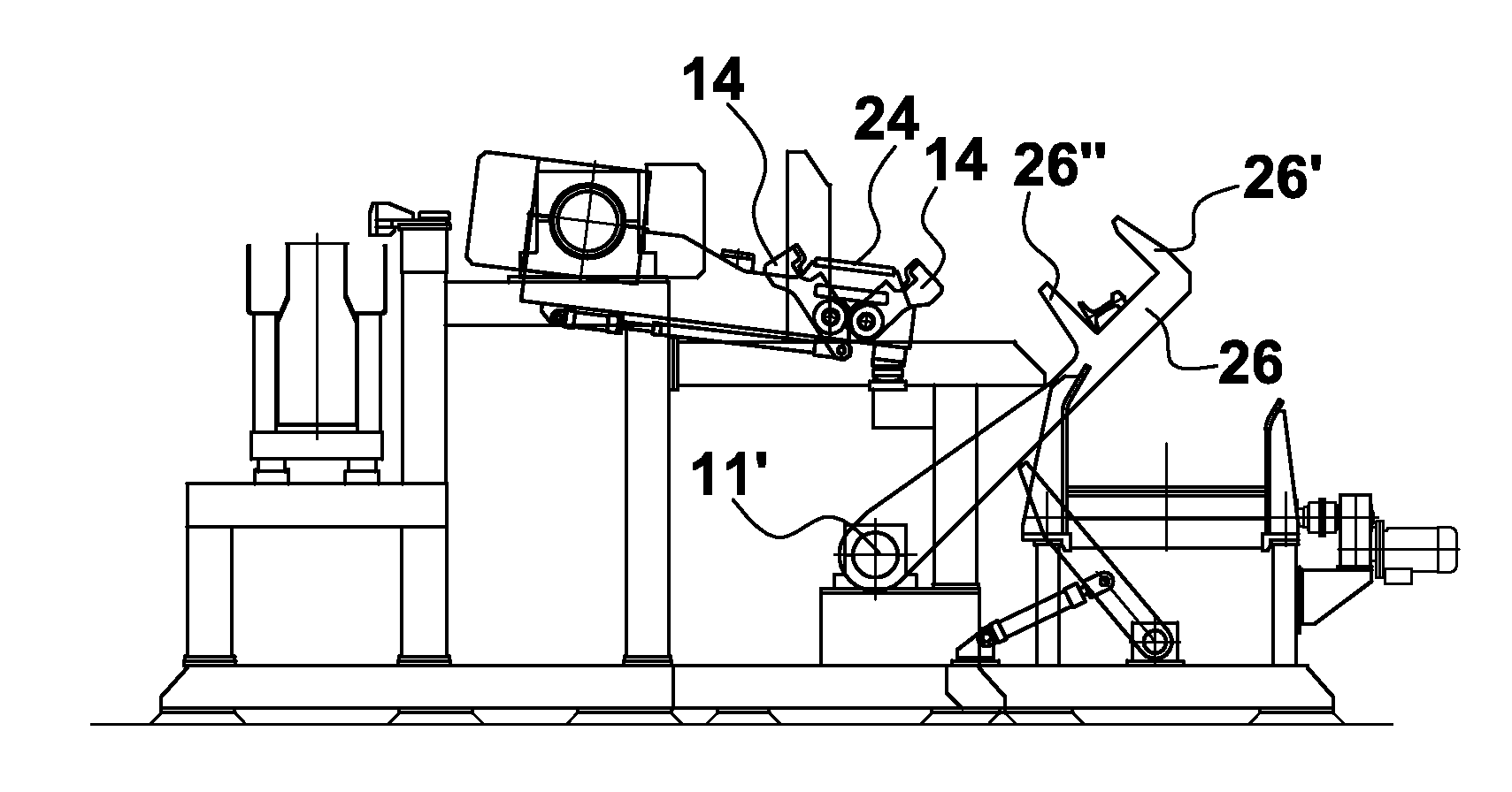
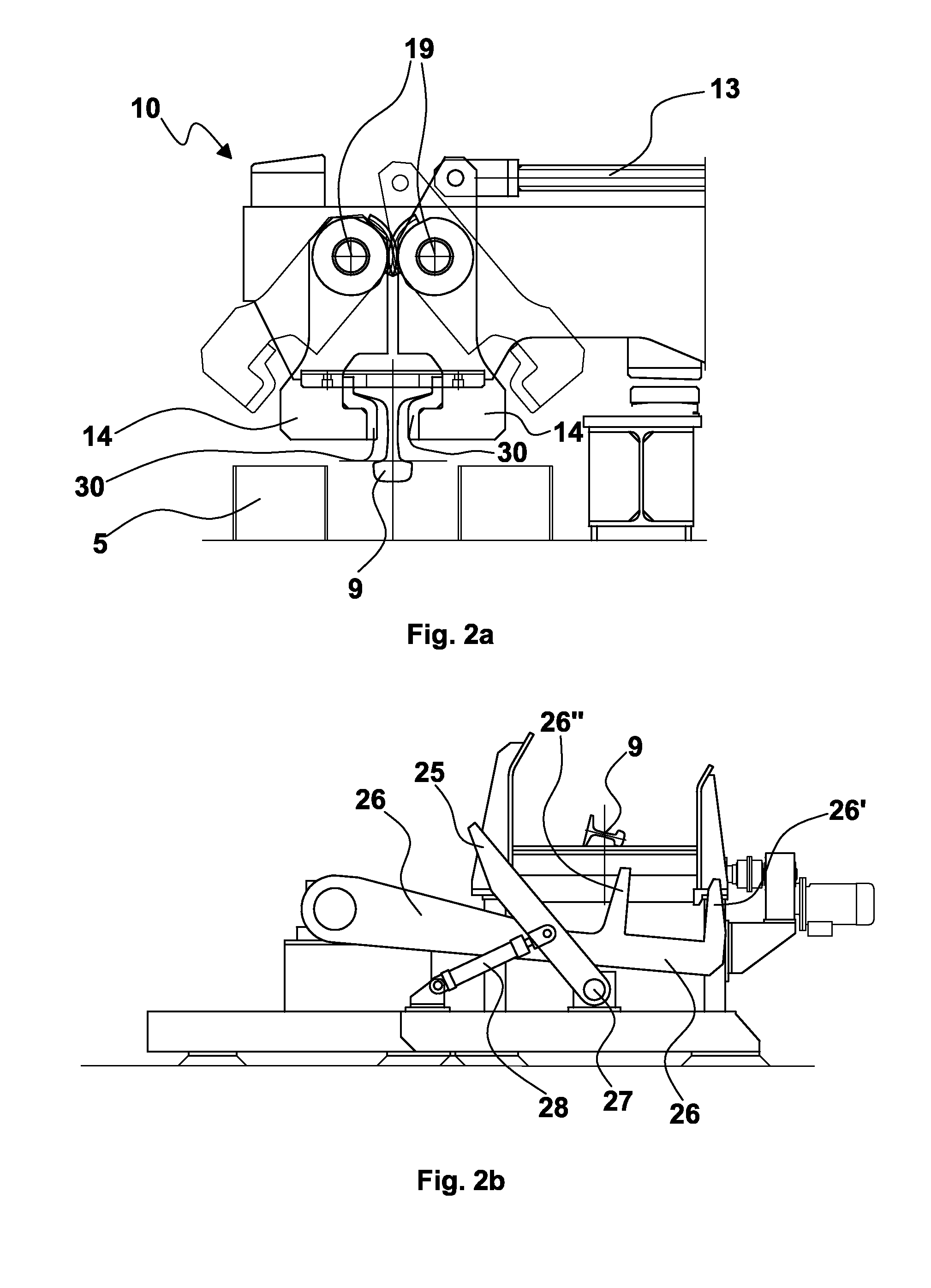
[0090]The handling process of the rails, carried out by means of the aforesaid first embodiment of the handling machine, comprises the following steps:[0091]1) unloading a rail 9 in a lopsided position, that is inclined on a side thereof, onto the roller table 3; during this step of receiving the rail, pushers 25 and levers 26 are in the respective external resting positions and underneath the roller table 3 (FIG. 3);[0092]2) actuating the pushers 25 by means of the hydraulic cylinders 28 so as to turn them by a predetermined angle, e.g. about 30°, in a first direction of rotation about respective pins 27, moving the rail 9, inclined on a side thereof, laterally with respect to the longitudinal middle plane of the roller table 3 itself, in particular on the side part of the roller table 3 distal from the tank 5 (FIG. 4);[0093]3) possibly actuating the second levers 26 so as to obtain a partial lifting thereof, with the bottoms of the spaces which accommodate rail 9 still under the p...

second embodiment

[0147]The main advantage obtained by this second embodiment of the handling machine is represented by a production rate of 27-28 rails / hour and an hourly production rate of 180-200 tons / hour.


PUM

PropertyMeasurementUnit
angleaaaaaaaaaa
angleaaaaaaaaaa
surface temperatureaaaaaaaaaa

Abstract

A handling machine for rails, arranged in line and immediately downstream of a rolling plant, which allows both to easily handle the rail for transferring it from the roller table to the thermal treatment zone, and to ensure an optimal gripping of the rail along its longitudinal extension, thus effectively contrasting its bending and variations while allowing a longitudinal movement of the rail caused by thermal shrinkage, thus avoiding damages both to the external surface of the rail and to the handlers. A rail handling process is also described, which optimizes moving, positioning along a roller table and maintaining the rail substantially rectilinear during the thermal treatment to which it is subjected.

Description

FIELD OF THE INVENTION[0001]The present invention relates to a handling machine for rails, in particular to a machine suitable for handling at least one rail in a thermal treatment plant for rail heads, said thermal treatment plant being arranged in line and immediately downstream of a rolling plant, and further relates to a rail handling process associated thereto.STATE OF THE ART[0002]The prior art has various solutions of thermal treatment plants for rolled rails, particularly aimed at hardening the head by means of quenching operation.[0003]Many of these systems are not arranged immediately after the rolling train outlet. This implies the need to stock the rolled rails and subsequently heat them before proceeding with the thermal quenching treatment, with high energy consumption and low efficiency.[0004]In other solutions, instead, these systems are arranged downstream of the rolling mill: the rolled rail is unloaded onto a roller table fixed to the ground; it is then drawn by h...

Claims


Application Information

Patent Timeline
Patent Type & Authority Patents(United States)
IPC IPC(8): B21B39/24C21D9/06B21B1/085C21D1/63
CPCC21D9/06B21B39/24B21B1/085C21D1/63C21D2221/00
Inventor POLONI, ALFREDOSCHREIBER, MARCO
Owner DANIELI & C OFF MEC SPA
Why Eureka
Try Eureka