
Coat/develop module with independent stations

a technology of developing module and dispense system, which is applied in the direction of program control, printer, and semiconductor/solid-state device testing/measurement. it can solve the problems of large processing time, large processing time, and inability to provide a number of different coatings, and achieve the effect of reducing system cost, complexity and footprint, and increasing system reliability

Active Publication Date: 2006-06-22
SCREEN SEMICON SOLUTIONS CO LTD
View PDF6 Cites 20 Cited by
  • Summary
  • Abstract
  • Description
  • Claims
  • Application Information

AI Technical Summary

Benefits of technology

[0018] Many benefits are achieved by way of the present invention over conventional techniques. For example, the present technique allows for sharing of some common components, reducing system cost, complexity, and footprint. Moreover, embodiments of the present invention provide for increased system reliability while reducing the number of redundant systems provided for each processing chamber. These and other benefits will be described in more detail throughout the present specification and more particularly below.

Problems solved by technology

As a result of the number and quality of the dispense nozzles in some of these modules, the cost of the dispense system may be much larger than the cost of the spin bowl.
Therefore, in some dispense systems, the most expensive system components, namely those included in the dispense apparatus, are idle during a significant fraction of the processing time.
The system as illustrated in U.S. Pat. No. 5,205,114 suffers from several problems.
First, the system provides only a single resist nozzle that dispenses a single resist.
Thus, the system does not provide a number of different coatings, including coatings of different materials.
Second, the only isolation provided between the spin chucks and the other items contained inside the casing is a cup surrounding each spin chuck.
Although this cup design may provide some containment for liquid particles scattered from the wafer surface, control of the atmosphere in the vicinity of the wafers is not provided by this design.

Method used


Image

  • Coat/develop module with independent stations
  • Coat/develop module with independent stations
  • Coat/develop module with independent stations

Examples


Embodiment Construction

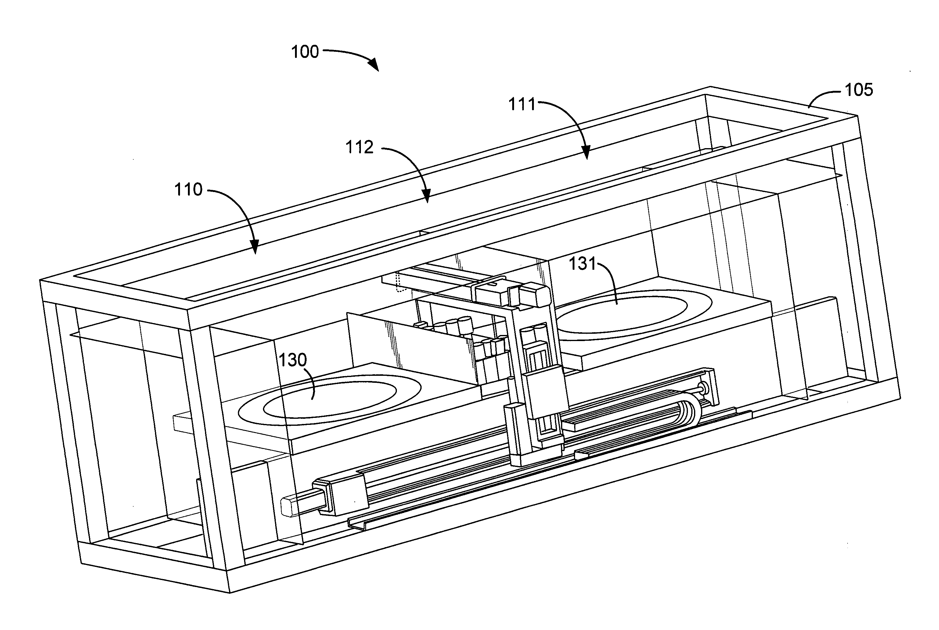
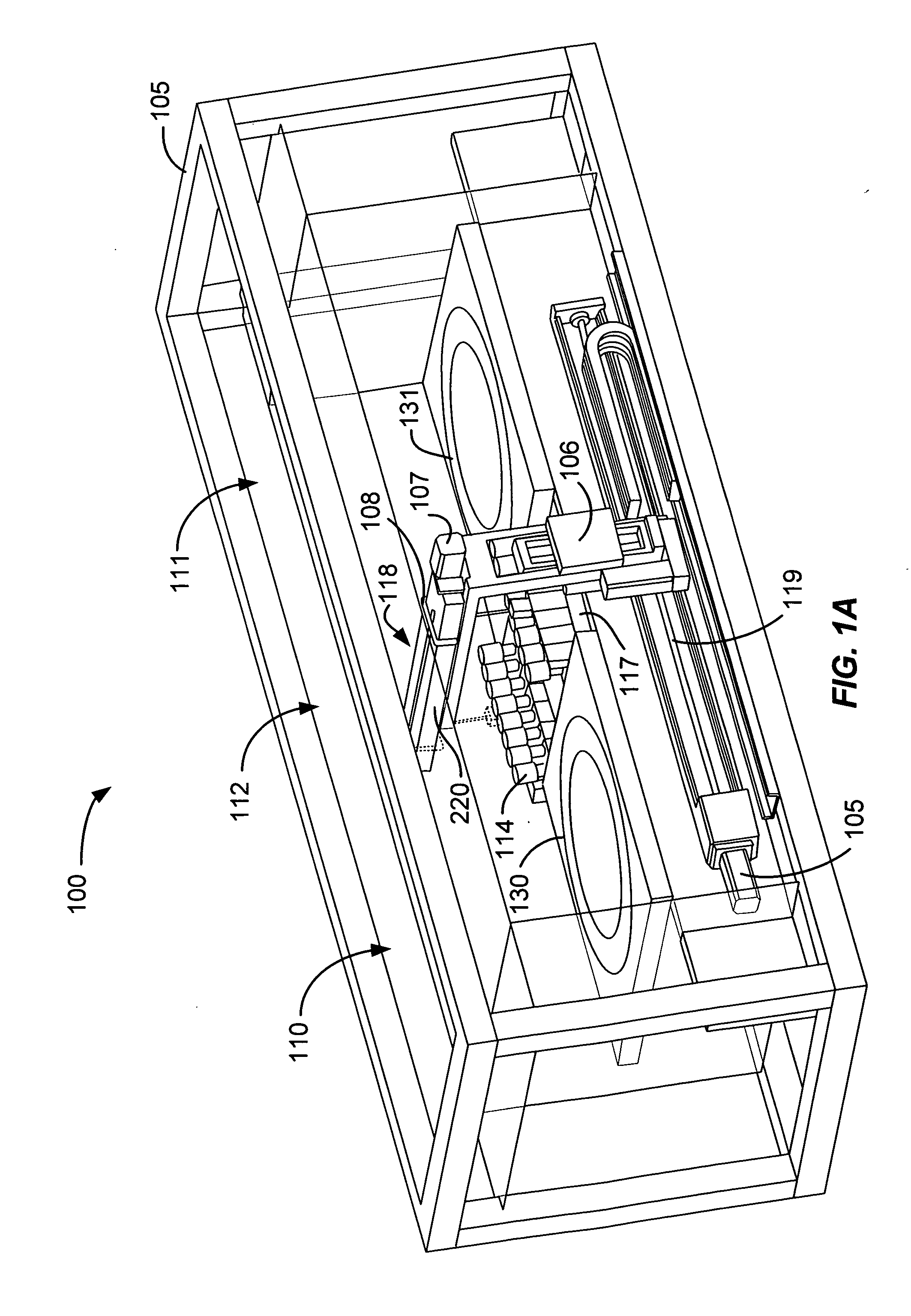
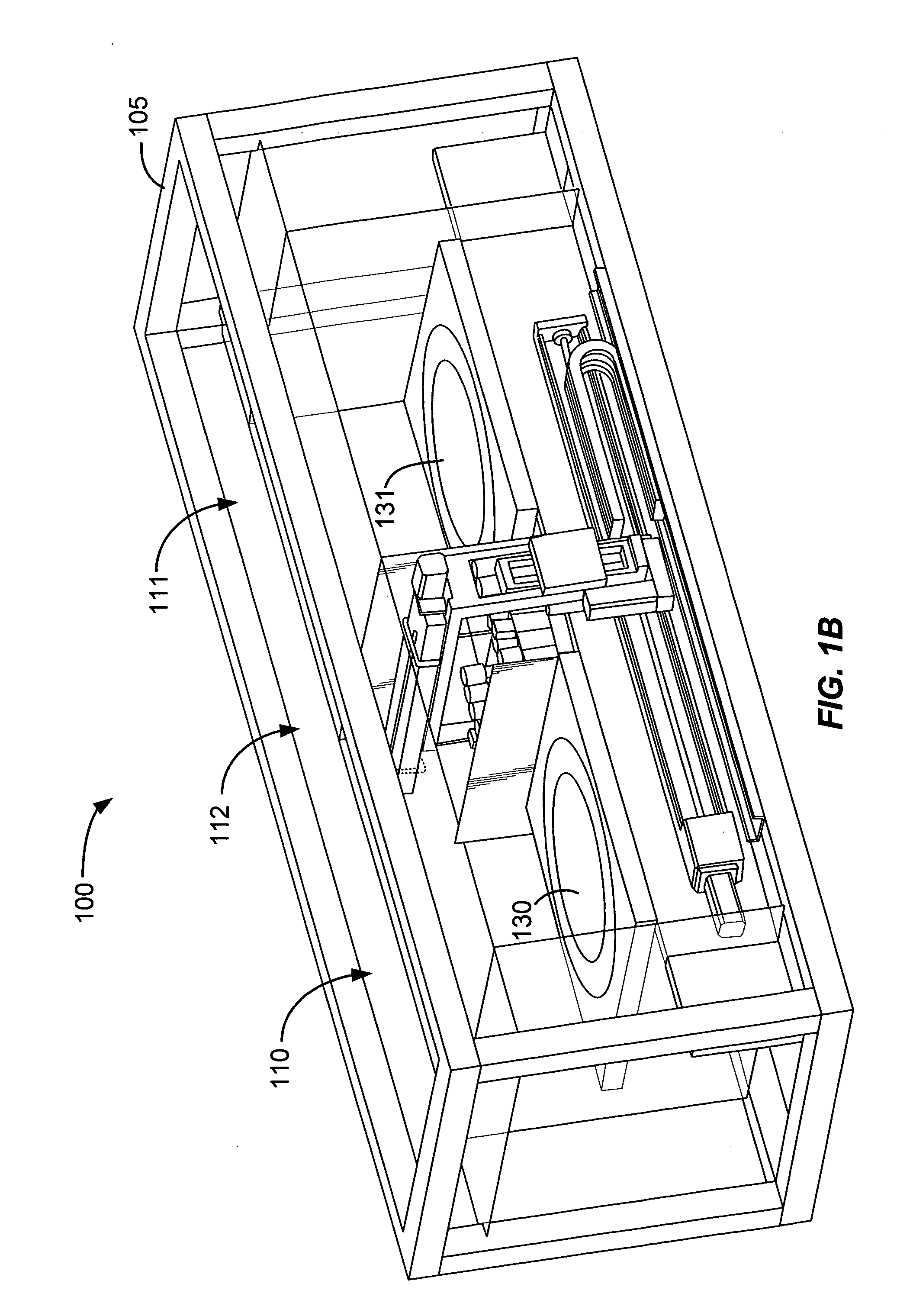
[0031] According to the present invention, techniques related to the field of semiconductor processing equipment are provided. More particularly, the present invention includes a method and apparatus for dispensing fluids onto a semiconductor substrate. Merely by way of example, the method and apparatus has been applied to two processing chambers in a coat / develop module including at least one dispense arm access shutter. But it would be recognized that the invention has a much broader range of applicability.

[0032]FIG. 7 is a plan view of one embodiment of a track lithography tool 710 that illustrates a number of the aspects of the present invention that may be used to advantage. One embodiment of the track lithography 710, as illustrated in FIG. 7, contains a front end module (sometimes referred to as a factory interface) 750, a central module 850, and a rear module (sometimes referred to as a scanner interface) 900. The front end module 750 generally contains one or more pod asse...


PUM

PropertyMeasurementUnit
dimensionsaaaaaaaaaa
temperatureaaaaaaaaaa
humidityaaaaaaaaaa

Abstract

An apparatus for dispensing fluid during semiconductor substrate processing operations. The apparatus includes a first processing chamber, a second processing chamber, and a dispense arm assembly. The apparatus further includes a dispense arm access shutter positioned between the first and second processing chambers and moveable between an open and a closed position. The dispense arm assembly can travel from the first processing chamber to the second processing chamber when the dispense arm assembly is in the open position. In an alternative embodiment, the apparatus also includes a central fluid dispense bank between the first and second processing chambers and a second dispense arm access shutter positioned between the first and second processing chambers, wherein the dispense arm access shutter is positioned between the first processing chamber and the central fluid dispense bank and the second dispense arm access shutter is positioned between the central fluid dispense bank and the second processing chamber.

Description

CROSS-REFERENCES TO RELATED APPLICATIONS [0001] This application claims the benefit of U.S. Provisional Application Ser. No. 60 / 639,109, filed Dec. 22, 2004, entitled “Twin Architecture For Processing A Substrate,” which is incorporated herein by reference. [0002] The following two regular U.S. patent applications (including this one) are being filed concurrently, and the entire disclosure of the other application is incorporated by reference into this application for all purposes. [0003] Application No. ______, filed ______, entitled “Coat / Develop Module with Shared Dispense” (Attorney Docket No. A9873 / T60100); [0004] Application No. ______ , filed ______, entitled “Coat / Develop Module with Independent Stations” (Attorney Docket No. A9873.2 / T60110);BACKGROUND OF THE INVENTION [0005] The present invention relates generally to the field of semiconductor processing equipment. More particularly, the present invention relates to a method and apparatus for dispensing fluids onto a semico...

Claims


Application Information

Patent Timeline
Patent Type & Authority Applications(United States)
IPC IPC(8): B05D5/00
CPCH01L21/67173H01L21/67745H01L22/26H01L21/67196H01L21/6831G03B27/32Y10S414/136H01L21/67109H01L21/68707H01L21/67742H01L21/6719G03F7/40Y10T29/53187H01L21/67161Y10S414/135H01L21/67754H01L21/67178G03D13/006H01L21/67748G05B2219/40476Y10T29/5323G05B19/41825H01L21/67184G05B2219/49137H01L21/6838H01L21/6715G05B2219/45031H01L21/67225Y02P90/02
Inventor ISHIKAWA, TETSUYAROBERTS, RICK
Owner SCREEN SEMICON SOLUTIONS CO LTD
Features
  • Generate Ideas
  • Intellectual Property
  • Life Sciences
  • Materials
  • Tech Scout
  • Unparalleled Data Quality
  • Higher Quality Content
  • 60% Fewer Hallucinations
Learn More