Golf club head and its manufacturing method

Inactive Publication Date: 2006-06-22
BRIDGESTONE SPORTS
View PDF24 Cites 13 Cited by
  • Summary
  • Abstract
  • Description
  • Claims
  • Application Information

AI Technical Summary

Problems solved by technology

However, when the metallic members were welded together by TIG welding or MIG welding, there was a problem that the weight control for the golf club head was difficult because a welding rod was employed and there was a sink in the weld zone.
Moreover, when the metallic members were welded together by laser welding or electron beam welding, there was a problem that the cost required for machining the metallic members was increased, because it was necessary to machine in advance the me

Method used


Image

  • Golf club head and its manufacturing method
  • Golf club head and its manufacturing method
  • Golf club head and its manufacturing method

Examples


first embodiment

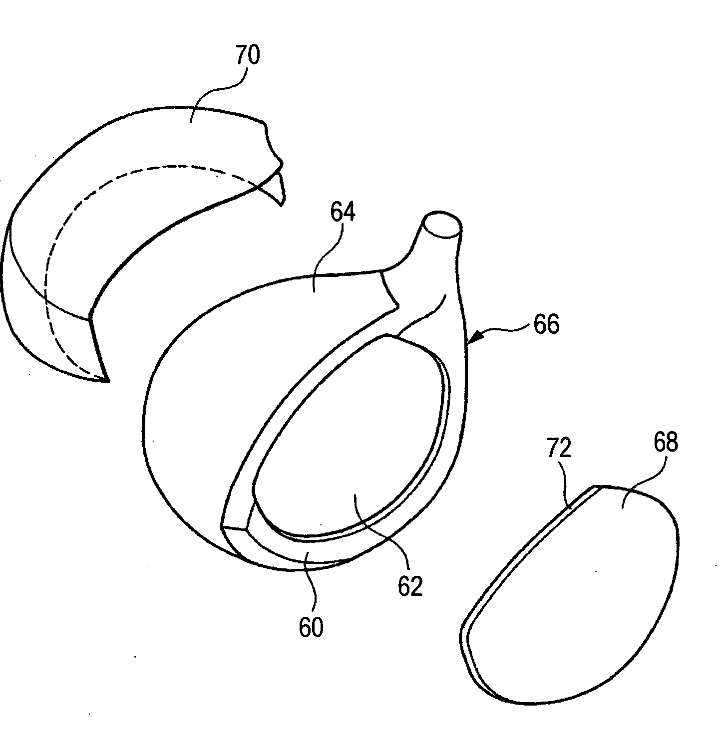
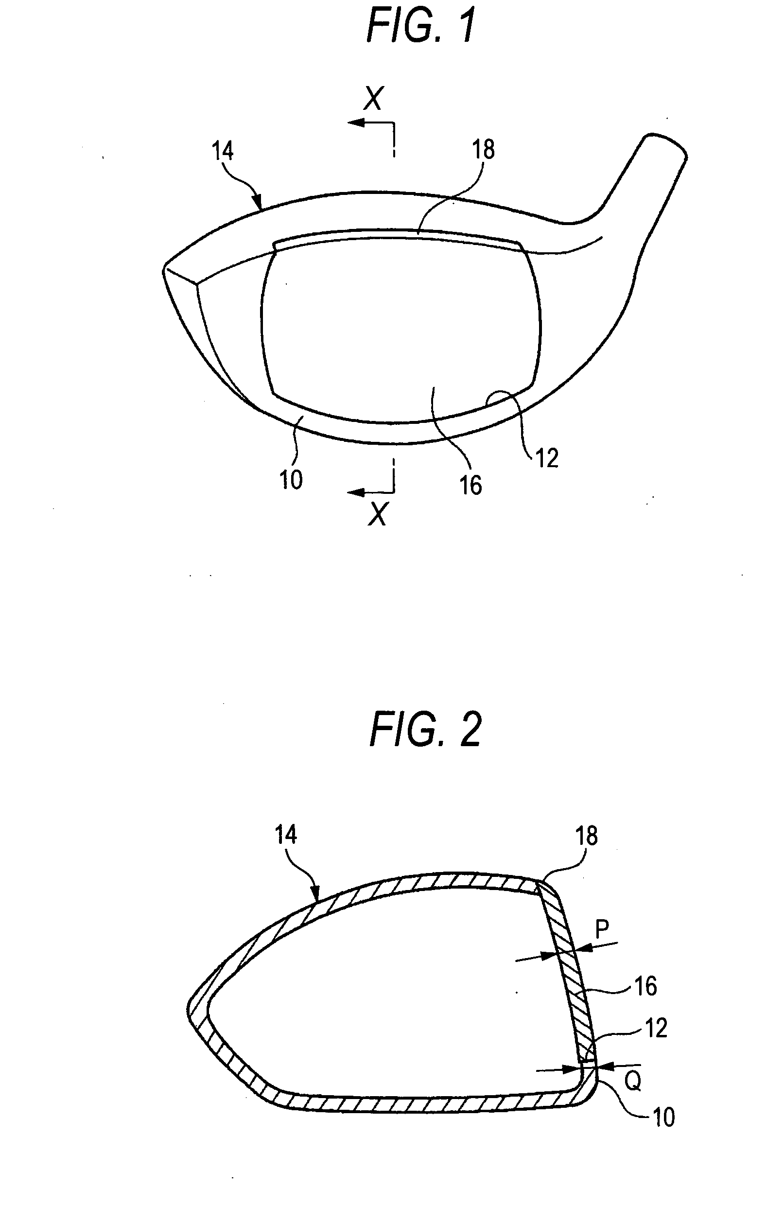
[0043]FIG. 1 is a perspective view showing a golf club head according to a first embodiment of the invention. FIG. 2 is a cross-sectional view of the golf club head of FIG. 1, taken along the line X-X in FIG. 1. FIG. 3 is a perspective view of a face member of the golf club head of FIG. 1. The golf club head of this embodiment is formed into the wood type golf club head having a hollow portion.

[0044] The golf club head of this embodiment includes a head main body 14 made of titanium alloy (specifically 6-4Ti) having a face opening portion 12 on a face side 10 and a face member 16 made of titanium alloy (specifically Ti735) for closing the face opening portion 12.

[0045] The golf club head of this embodiment has an upper edge of the face opening portion 12 and an upper edge of the face member 16 extending to a crown portion. Accordingly, when the face portion 16 is fixed to a peripheral portion of the face opening portion 12 for the head main body 14, an upper edge 18 of the face me...

second embodiment

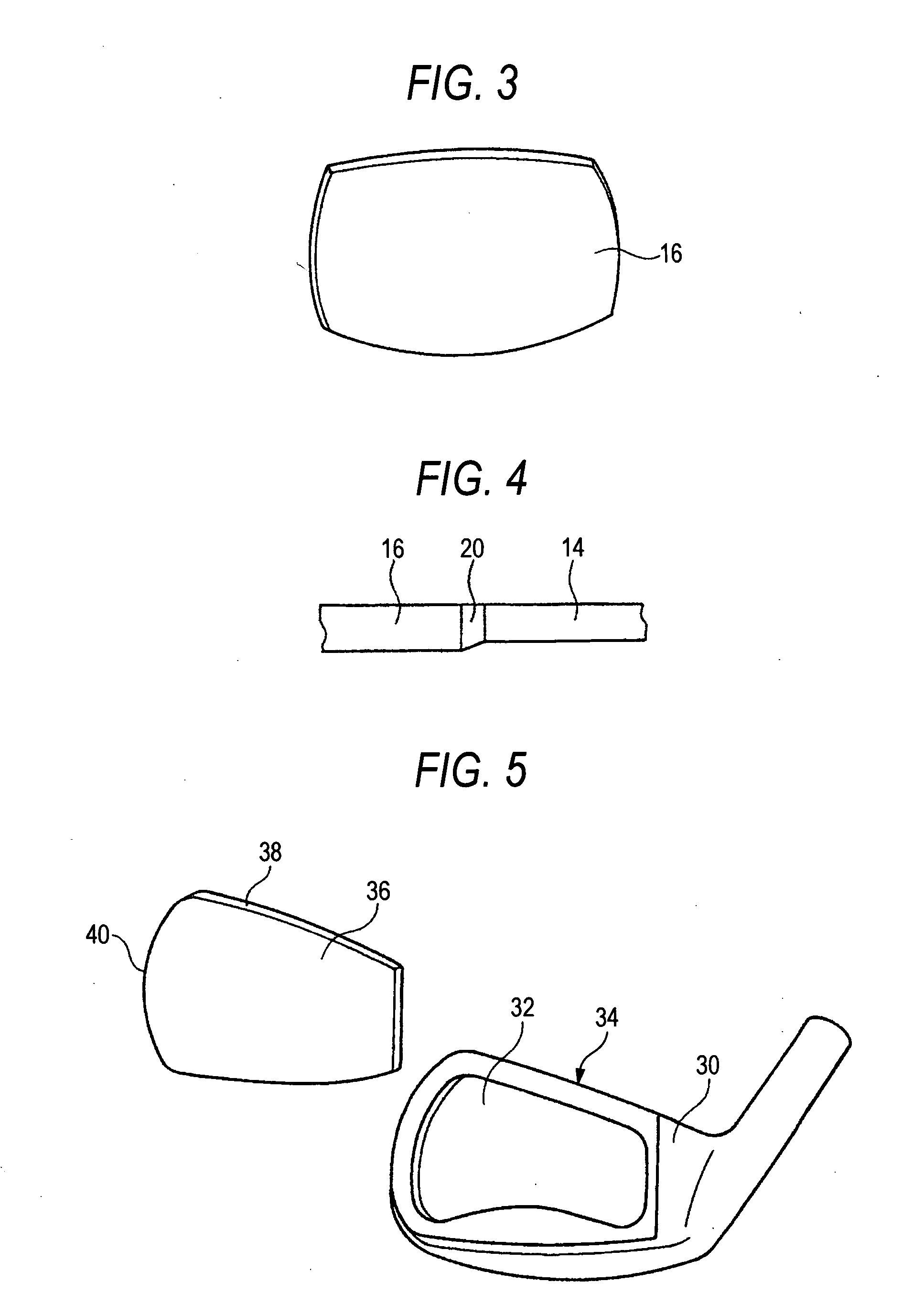
[0048]FIG. 5 is an exploded perspective view showing a golf club head according to a second embodiment of the invention. The golf club head of this embodiment is formed into the iron type golf club head.

[0049] The golf club head of this embodiment includes a head main body 34 (cast member of SUS630) having a face opening portion 32 on a face side 30 and a face member 36 (rolled member of SUS630) for closing the face opening portion 32.

[0050] In the golf club head of this embodiment, when the face member 36 is fixed to a peripheral portion of the face opening portion 32 for the head main body 34, an upper edge 38 of the face member 36 constitutes a part of the top blade portion for the golf club head and a leading edge 40 of the face member 36 constitutes a part of the toe portion for the golf club head.

[0051] In the golf club head of this embodiment, the thickness of the face member 36 is greater by 0.1 mm than the thickness of the peripheral portion of the face opening portion f...

third embodiment

[0053]FIG. 6 is a perspective view showing a golf club head according to a third embodiment of the invention. The golf club head of this embodiment is formed into the iron type golf club head.

[0054] The golf club head of this embodiment includes a head main body 52 (cast member of SUS630) having a face opening portion (not shown) on a face side 50 and a face member 54 (rolled member of SUS630) for closing the face opening portion. FIG. 6 shows a state where the head main body 52 and the face member 54 are fixed together.

[0055] In the golf club head of this embodiment, when the face member 54 is fixed to a peripheral portion of the face opening portion for the head main body 52, a lower edge 56 of the face member 54 constitutes a part of the sole portion for the golf club head and a leading edge 58 of the face member 54 constitutes a part of the toe portion for the golf club head.

[0056] In the golf club head of this embodiment, the thickness of the face member 54 is greater by 0.1...


PUM

PropertyMeasurementUnit
Thicknessaaaaaaaaaa

Abstract

A golf club head includes a first metallic member, a second metallic member having different thickness from the first metallic member, and a part where the first and second metallic members are welded by plasma welding, laser welding or electron beam welding. A gap between the first and second metallic members is filled up with another metal material besides the first and second metallic members.

Description

BACKGROUND OF THE INVENTION [0001] 1. Field of the Invention [0002] The present invention relates to a golf club head having a part where the metallic members with different thickness are welded by plasma welding, laser welding or electron beam welding and its manufacturing method. [0003] 2. Description of the Related Art [0004] Conventionally, there is a golf club head having a part where the metallic members are welded together, in which a face, a crown, a sole, and a hosel are welded by TIG welding, MIG welding, laser welding or electron beam welding (refer to JP-A-5-15620). [0005] However, when the metallic members were welded together by TIG welding or MIG welding, there was a problem that the weight control for the golf club head was difficult because a welding rod was employed and there was a sink in the weld zone. [0006] Moreover, when the metallic members were welded together by laser welding or electron beam welding, there was a problem that the cost required for machining...

Claims


Application Information

Patent Timeline
IPC IPC(8): A63B53/04A63B102/32
CPCA63B53/0466A63B53/047A63B53/0475A63B2053/0408A63B2053/0416A63B2209/02A63B2053/042B23K15/0073B23K26/203B23K2203/04B23K2203/10A63B2209/00B23K10/02B23K26/211B23K2103/05B23K2103/10A63B53/042A63B53/0408A63B53/0416A63B53/0458A63B53/0425
Inventor IMAMOTO, YASUNORIYAMAGISHI, HISASHIMATSUNAGA, HIDEO
Owner BRIDGESTONE SPORTS
Why Eureka
Try Eureka