Storage system and snapshot data preparation method in storage system

a storage system and snapshot data technology, applied in the field of storage system and snapshot data preparation method in storage system, can solve the problems of increasing the amount of pool region that is used, dispersing the burden of snapshot data preparation between the host, and difficult to predict the extent of future pool region us

Inactive Publication Date: 2006-06-22
HITACHI LTD
View PDF7 Cites 60 Cited by
  • Summary
  • Abstract
  • Description
  • Claims
  • Application Information

AI Technical Summary

Benefits of technology

[0008] Accordingly, it is an object of the present invention to prevent the data space used to save data prior to updating from becoming filled with saved data from the primary (logical) volume so that snapshot data preparation processing ends abnormally during snapshot data preparation in a storage system.

Problems solved by technology

As a result, the burden of snapshot data preparation is dispersed between the host device and the storage system.
However, when the amount of updated data is large, the amount of the pool region that is used is also unavoidably increased to a corresponding extent, and especially when a plurality of pairs of primary (logical) volumes and secondary (logical) volumes are formed, and snapshot data of these volumes of the like is prepared, it is difficult to predict the extent of future pool region use.
In some cases, furthermore, the pool region may become filled with saved data from the primary (logical) volume, so that the snapshot data preparation processing ends abnormally.

Method used


Image

  • Storage system and snapshot data preparation method in storage system
  • Storage system and snapshot data preparation method in storage system
  • Storage system and snapshot data preparation method in storage system

Examples


first embodiment

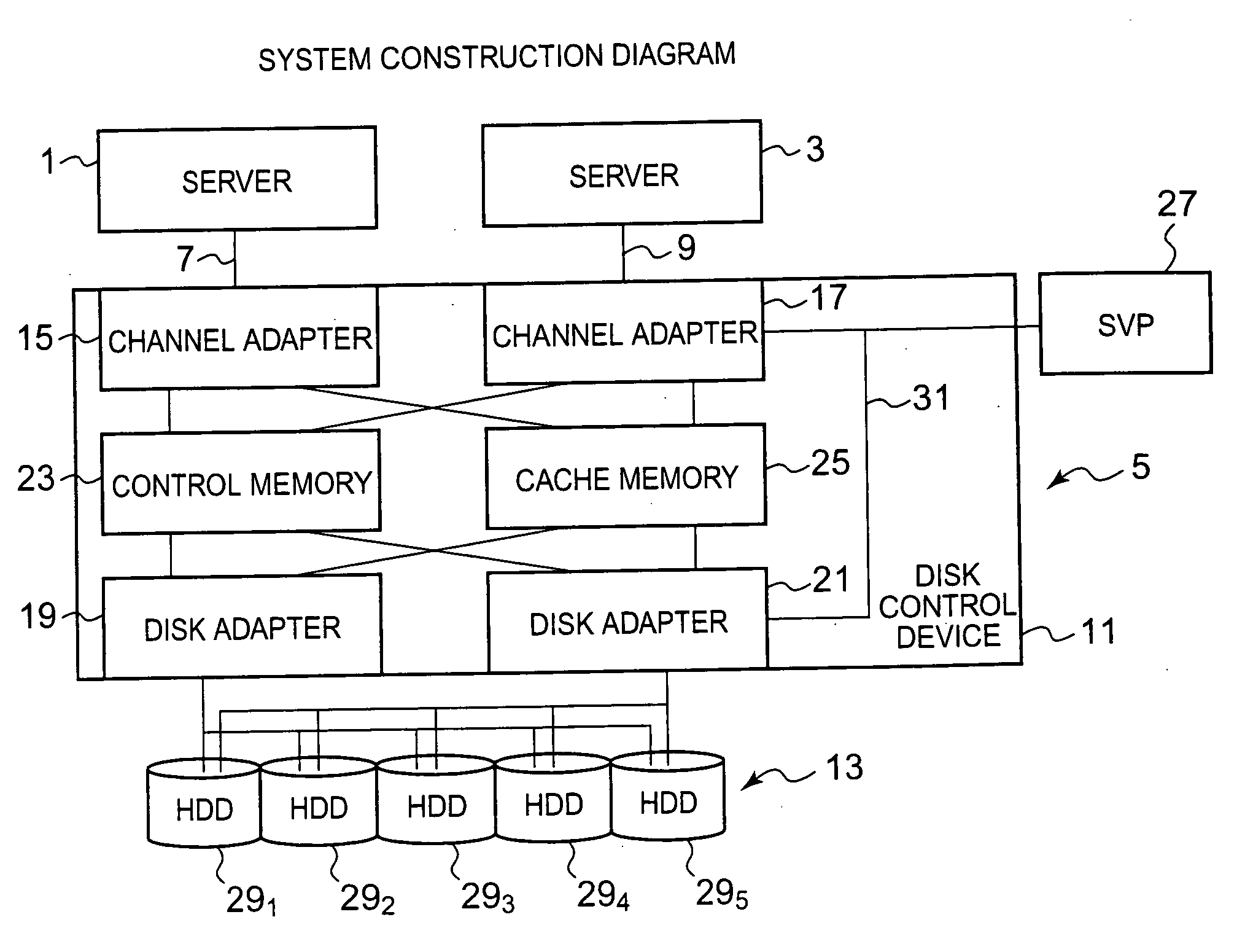
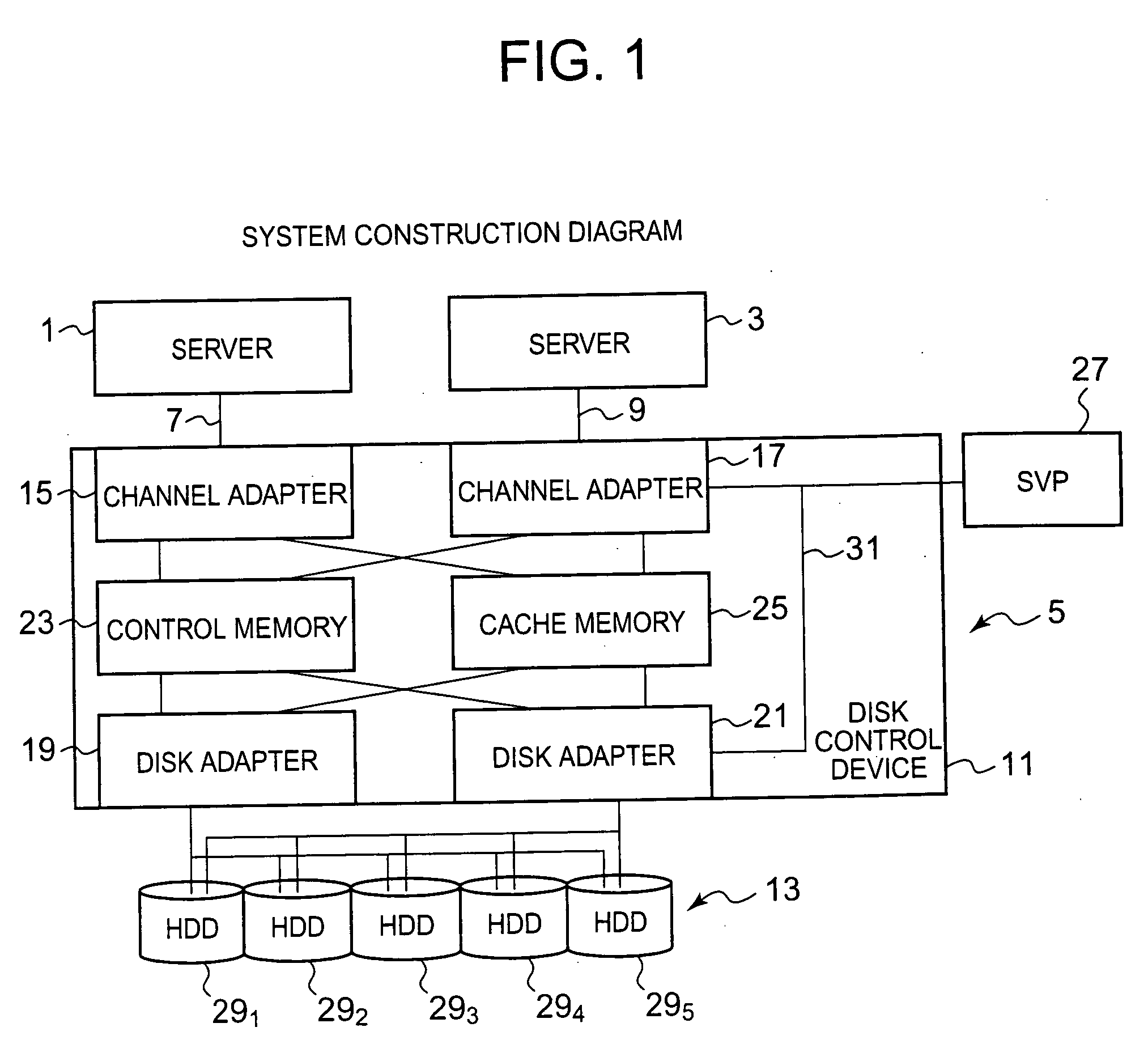
[0063]FIG. 1 is a block diagram showing the overall construction of an information processing system comprising a storage system which constitutes the present invention.

[0064] In FIG. 1, the host devices, i.e., servers 1 and 3, are computer devices comprising information processing resources such as a CPU, memory and the like. For example, the servers 1 and 3 have information input means such as a keyboard switch, pointing device, microphone or the like (not shown in the figures), and information output means such as a monitor display, speaker or the like (not shown in the figures). Furthermore, for example, the servers 1 and 3 have application programs (not shown in the figures) such as data base software or the like using a storage region provided by a storage system 5, and an adapter (not shown in the figures) used to access the storage system 5 via communications networks 7 and 9.

[0065] For example, depending on the case, an LAN (local area network), an SAN (storage area networ...

second embodiment

[0113] Accordingly, in view of the above, the present invention (described below) has been proposed.

[0114]FIG. 11 is an explanatory diagram showing one example of the volume control information that is stored in the control memory (23) of the storage system 5 of the second embodiment of the present invention. Furthermore, the storage system in this embodiment, and the information processing system comprising this storage system, have the same construction as the storage system of the first embodiment of the present invention shown in FIG. 1, and the information processing system comprising this storage system. Accordingly, a graphic illustration and detailed description of the storage system in this embodiment, and of the information processing system comprising this storage system, are omitted.

[0115] In the present embodiment, the volume control information shown in FIG. 11 differs from the volume control information shown in FIG. 3 in that an HDD number 69 is stored instead of th...

third embodiment

[0128] Accordingly, in view of the above, the present invention (described below) has been proposed.

[0129]FIG. 14 is an explanatory diagram showing one example of the volume control information that is stored in the control memory (23) of the storage system (5) of the third embodiment of the present invention. Furthermore, the storage system in the present embodiment, and the information processing system comprising this storage system, have the same construction as the storage system of the first embodiment of the present invention shown in FIG. 1, and the information processing system comprising this storage system. Accordingly, a graphic illustration and detailed description of the storage system in the present embodiment, and of the information processing system comprising this storage system, are omitted.

[0130] In the present embodiment, the volume control information shown in FIG. 14 differs from the volume control information shown in FIG. 3 and the volume control informatio...


PUM


Abstract

The present invention is devised so that snapshot data preparation processing does not end abnormally as a result of the pool region becoming full with saved data from the primary logical volume during snapshot data preparation. When the CHA receives a snapshot data preparation request, the CHA checks whether or not update information is present in the logical volume that is the object of this data preparation. If such information is present (YES in S51), a check is made from the number of slots in the in the volume control information and the updating amount count value in the update information in order to ascertain whether or not the proportion of the updating amount relative to the number of slots is equal to or greater than the threshold value in the threshold value control information (S52). If this proportion is equal to or greater than the threshold value (YES in S52), the update information is initialized (S53), and physical snapshot control is started (S54). If such is not the case (NO in S52), the update information is initialized (S55), and logical snapshot control is started (S56).

Description

CROSS-REFERENCE TO PRIOR APPLICATION [0001] This application relates to and claims priority from Japanese Patent Application No. 2004-353153, filed on Dec. 6, 2004, the entire disclosure of which is incorporated herein by reference. BACKGROUND OF THE INVENTION [0002] 1. Field of the Invention [0003] The present invention relates to a storage system which exchanges data with a higher-level device, and a snapshot data preparation method in this storage system. [0004] 2. Description of the Related Art [0005] Conventionally, in information processing systems comprising a storage system, a proposal has been made with the object of reducing the load on host devices relating to snapshot data control, and increasing the speed of the storage system. In this proposal, when a host device desires the preparation of snapshot data, this host device transmits an instruction indicating a snapshot data preparation request to a storage system, the control part (disk control device) of the storage sys...

Claims


Application Information

Patent Timeline
Patent Type & Authority Applications(United States)
IPC IPC(8): G06F11/00
CPCG06F3/0608G06F3/0659G06F3/0689G06F11/0727G06F11/076G06F11/1471
Inventor WATANABE, HARUAKI
Owner HITACHI LTD
Why Eureka
Try Eureka