Dehumidifying of air within switch cabinet for a wind turbine by means of peltier element

a technology of switch cabinet and wind turbine, which is applied in the direction of drying, engine fuction, light and heating apparatus, etc., can solve the problems of significant derogation of wind turbine operation, low rate of desiccants for binding air humidity, and inability to ensure the reliability of water deposition on the circuit elements, etc., to achieve small power consumption, improve operational reliability, and air flow

Inactive Publication Date: 2006-06-29
GE WIND ENERGY
View PDF99 Cites 22 Cited by
  • Summary
  • Abstract
  • Description
  • Claims
  • Application Information

AI Technical Summary

Benefits of technology

[0006] Surprisingly, it was found that generating an air flow contributes to the prevention of water deposition onto circuit elements. This air flow can be generated with comparatively small power consumption by using a simple fan. A further improvement of operational reliability can be achieved when the drying arrangement further includes at least one heater for heating the air in the region of the at least one circuit element, because then the water vapor absorption capacity of the air is increased in the region of the at least one circuit element and, thus, the risk of condensation on the circuit element is reduced.
[0007] According to a preferred embodiment of the switch cabinet according to the present invention, the drying arrangement includes a cooling element for separating water from the passing air, said cooling element being spaced from said at least one circuit element, and a drain element for draining the separated water out of the switch cabinet. Thus, the air humidity within the switch cabinet is effectively reduced so that the risk of water deposition onto the at least one circuit element is counteracted. Thereby, the reduction of air humidity within the switch cabinet can be achieved in a particularly effective manner when the flow generating device is operable to generate an air flow, which circulates within said switch board and moves past the at least one circuit element as well as said cooling element, so that the air circulating within the switch board continously absorbs humidity which is then separated at the cooling element and is drained out of the switch cabinet through a drain opening.

Problems solved by technology

However, this measure is associated with high power consumption so that the profitability of wind turbine operation is significantly derogated.
However, the intake capacity of such desiccants is limited so that they need to be replaced frequently, which poses problems particularly when the switch cabinet is disposed at a height of 100 m or more.
Furthermore, the reaction rate of desiccants for binding of air humidity is relatively low so that reliable prevention of water depositions onto the circuit elements cannot be achieved by this method.

Method used


Image

  • Dehumidifying of air within switch cabinet for a wind turbine by means of peltier element
  • Dehumidifying of air within switch cabinet for a wind turbine by means of peltier element
  • Dehumidifying of air within switch cabinet for a wind turbine by means of peltier element

Examples


first embodiment

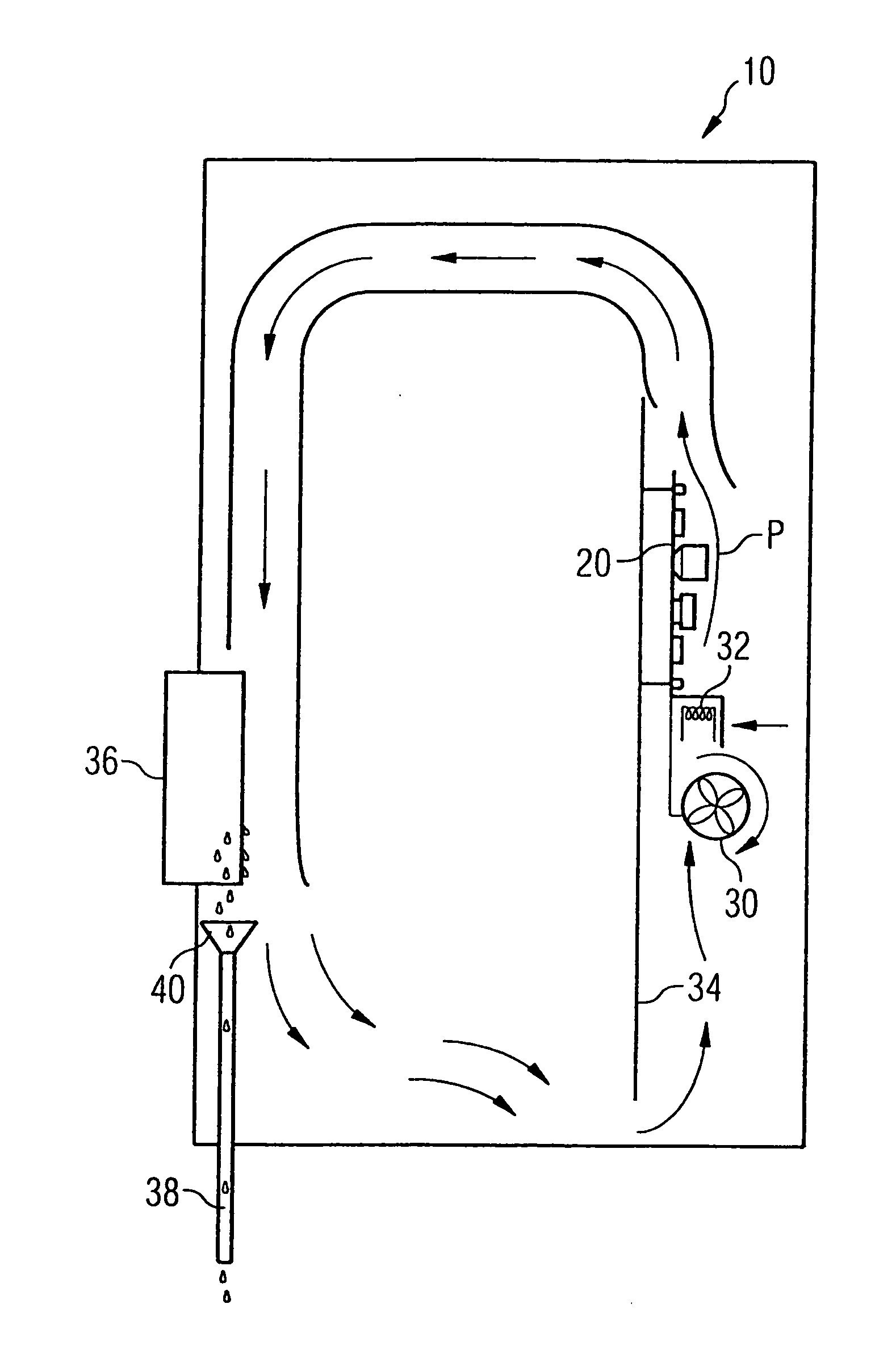
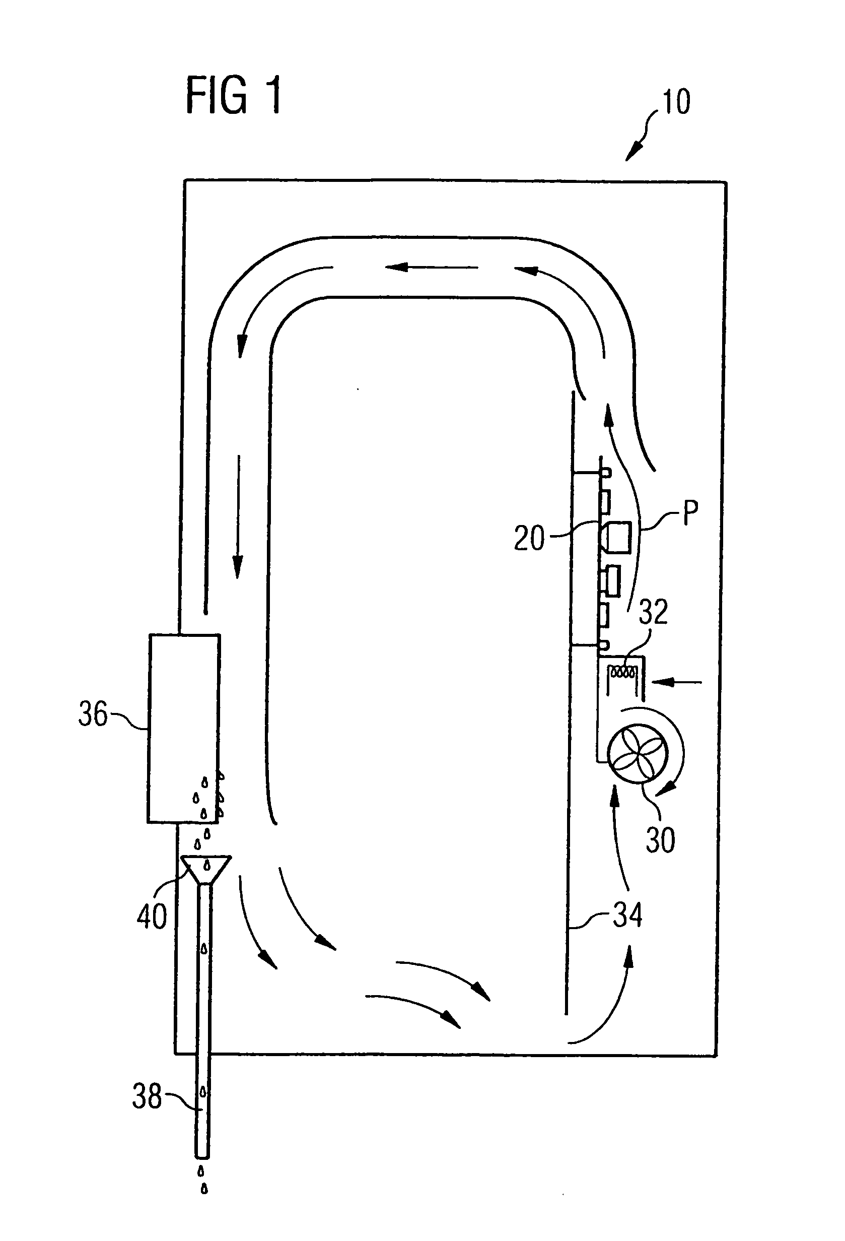
[0012] According to FIG. 1, a switch cabinet for a wind turbine according to the present invention can be realized as a fully enclosed switch cabinet having a cabinet door which is closed during operation. A number of electric and / or electronic circuit elements is situated within the switch cabinet, wherein said circuit elements can be disposed on one or more circuit boards 20 as is exemplarily shown in FIG. 1. Furthermore, a drying arrangement is also accomodated in switch cabinet 10, wherein, according to the embodiment of the present invention shown in FIG. 1, said drying arrangement includes a fan 30 disposed below the circuit board, a heater 32 disposed upstream with respect to the air flow generated by said fan 30 and behind the fan 30, a flow guide plate 34 serving as a support for circuit board 20, and a cooling element 36 disposed upstream said circuit board and at that side of the flow guide plate 34 that does not face the circuit board.

[0013] An air flow directed towards ...
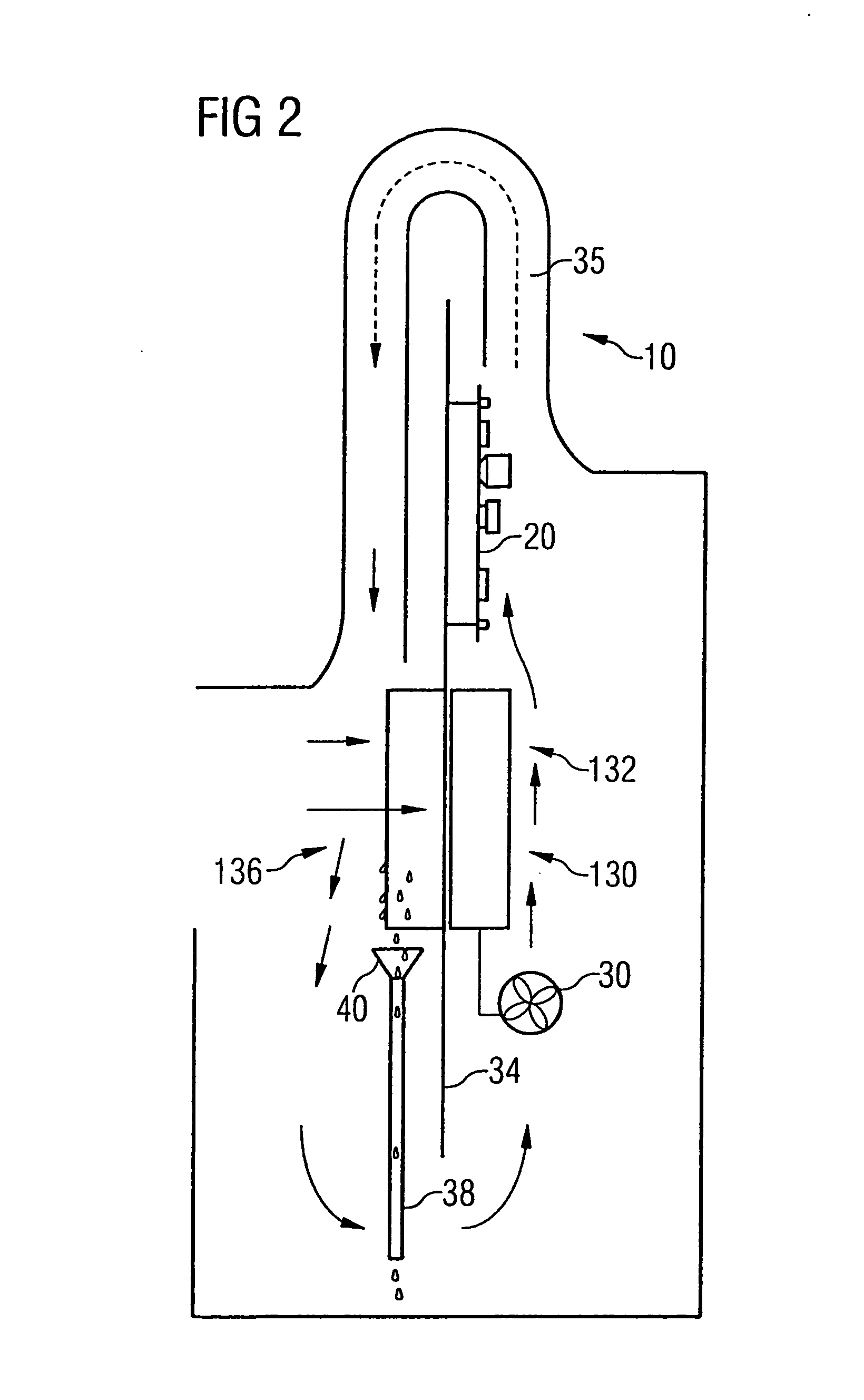
second embodiment

[0016] The second embodiment according to the present invention shown in FIG. 2 differs from the embodiment shown in FIG. 1 mainly in that a heater in the form of a Peltier element 130 is used instead of the heater in the form of a heating coil. The Peltier element 130 is arranged so that its warmer side 132, in an operating condition, is disposed on the same side of flow guide plate 34 as circuit board 20. The air heated by the warmer side 132 of Peltier element 130 moves past circuit board 20 and is deflected by a flow conduit 35 so that it moves past the cooler side 136, in an operating condition, of Peltier element 130 at the side of flow guide plate 34 not facing circuit board 20. Thereby, the Peltier element is used as an active cooling element, wherein the water contained in the air circulating within the switch cabinet condenses at its cooler side and is collected by means of a hopper 40 and is subsequently drained out of the switch cabinet via a drain conduit 38. The arrang...


PUM


Abstract

The invention relates to a switch cabinet for a wind turbine with at least one circuit element accommodated in said switch cabinet and a drying arrangement for preventing water depositions onto the at least one circuit element, wherein the drying arrangement includes a device for generating an air flow in a region of the at least one circuit element, the device including a peltier element.

Description

FIELD OF THE INVENTION [0001] The present invention relates to a switch cabinet for a wind turbine with at least one circuit element accomodated in said switch cabinet and a drying arrangement for preventing water deposition onto said at least one circuit element as well as to a method for operating a wind turbine using such a switch cabinet. BACKGROUND OF THE INVENTION [0002] The operating parameters of modern wind turbines, like e.g. blade angle, total orientation of the rotor and / or adjustments of the generator used for power generation, are electronically controlled. The electric or electronic circuit elements utilized therefor are usually accomodated in a switch cabinet mounted to the machine nacelle, which is disposed in a height of up to 100 m. This switch cabinet is subject to atmospheric influences. To guarantee reliable operation of the wind turbine, water should not be deposited onto the electric or electronic circuit elements during any atmospheric condition. [0003] In p...

Claims


Application Information

Patent Timeline
Patent Type & Authority Applications(United States)
IPC IPC(8): F26B3/00F03D11/00H05K5/02
CPCF03D11/00F05B2260/20H05K5/0213Y02E10/722F03D80/60Y02E10/72H05K5/0212
Inventor ACHENBACH, PATRICK
Owner GE WIND ENERGY
Why Eureka
Try Eureka