Bleed leak detection system

a leak detection and leak detection technology, applied in the field of space, can solve the problems of hot air leakage from the duct interior to the insulation blanket, and the air flow velocity cannot be sustained,

Active Publication Date: 2006-06-29
SENIOR IP GMBH
View PDF15 Cites 26 Cited by
  • Summary
  • Abstract
  • Description
  • Claims
  • Application Information

AI Technical Summary

Benefits of technology

[0010] When the metallic duct develops a crack, the hot air leaks from duct interior to the insulation blanket. The insulation blanket changes the characteristics of the hot air leakage 1) by absorbing the thermal energy and reducing the air temperature; 2) by reducing the effective pressure due to pressure drop; and 3) by reducing the volume by diffusing the air in the annulus between metal duct and insulation shell throughout the length of the duct.
[0013] Therefore, in a second, and preferred embodiment of the invention, a manifold has been added between the cuff and the sensor wires to direct the stream of hot air directly from the vent hole to the sensor wires without the loss of heat to the ambient environment. The design of the preferred embodiment consists of adding a manifold block and a manifold cap installed on top of the cuff and inline with the vent hole in the cuff. The manifold block is designed to route the hot air from a single conduit in the manifold, to a “Y” where the conduit divides into two conduits, which lead directly to the sensor sires. Hot air impingement is accomplished by installing a cap on the manifold block that secures each of the sensor wires in a channel groove. The channel groove in the cap for each sensor wire is designed to align with the outlet of the one of the two conduits running through the manifold from the “Y”. As such, the hot air flows directly from the vent hole to the sensor wires with sufficient heat to trip the sensor wires.

Problems solved by technology

If sufficient air pressure exists at low volume, air flow velocity cannot be sustained once the volume is quickly depleted.
When the metallic duct develops a crack, the hot air leaks from duct interior to the insulation blanket.

Method used


Image

  • Bleed leak detection system
  • Bleed leak detection system
  • Bleed leak detection system

Examples


Embodiment Construction

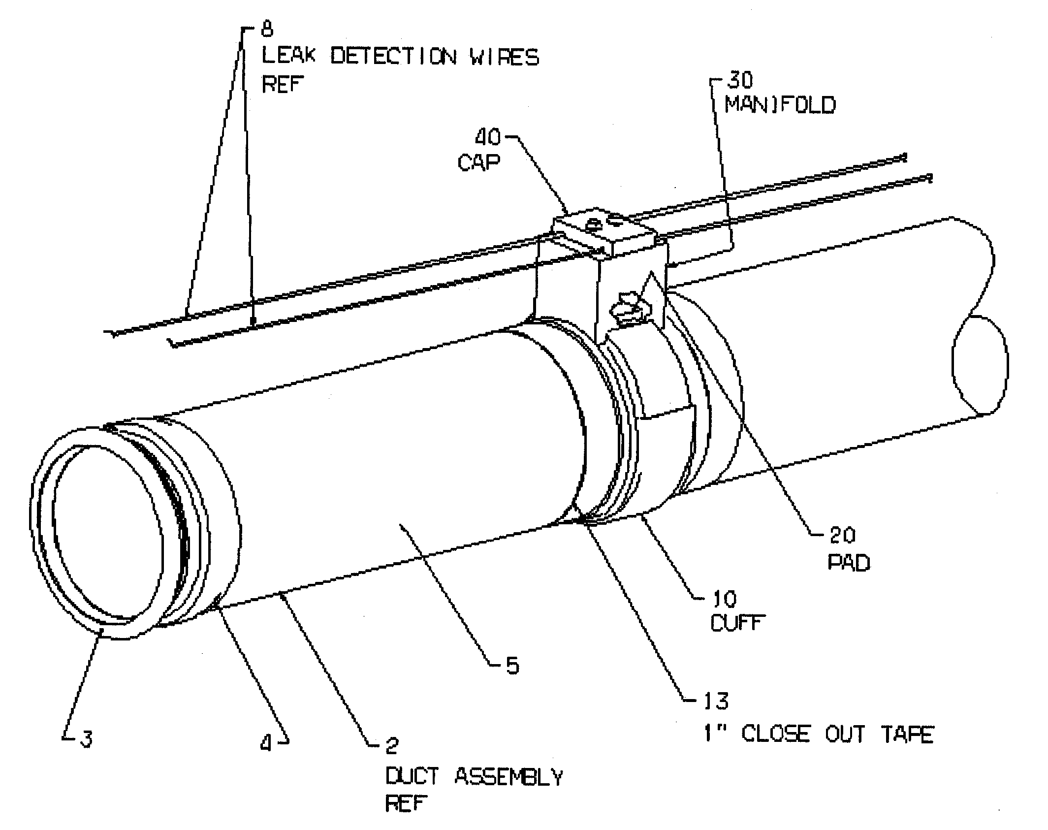
[0020] A typical duct assembly 2 of the type with which the invention is intended to be used is shown in FIG. 1 and consists of an inner metal duct 3, typically composed of steel and 1.00″ to 4.00″ in diameter, covered by insulation blanket 4, and secure by outer insulation shell 5. Insulation blanket 4 and outer insulation shell 5 are composed of materials as previously discussed.

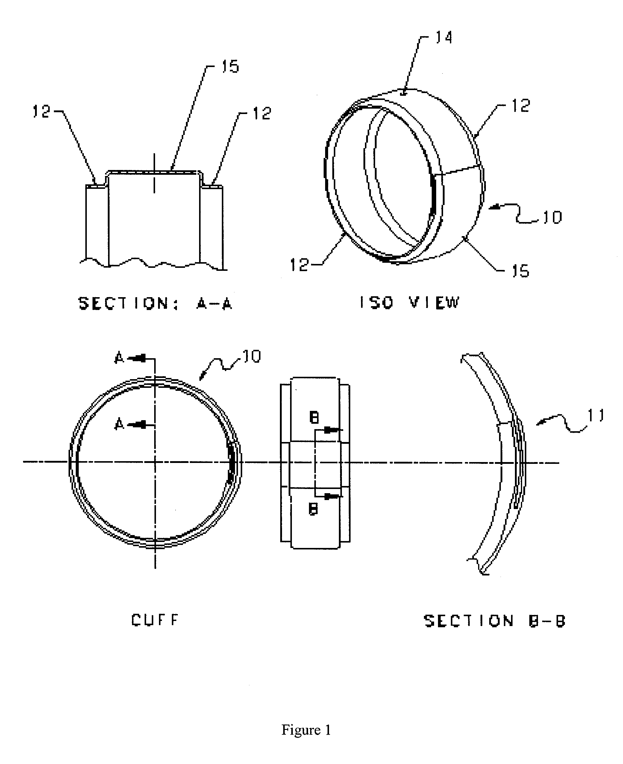
[0021]FIG. 1 shows the cuff 10 portion of the invention. Cuff 10 is positioned circumferentially around outer insulation shell 5 of duct assembly 2 as shown in FIG. 1. Preferably, cuff 10 is composed of multiple plies of fiberglass impregnated with silicon rubber, and, in the most referred embodiment, three plies are used to avoid having cuff 10 rupture due to excessive pressure build-up when installed in situ around duct assembly 2. Before securing cuff 10 to duct assembly 2, at least outer insulation shell 5 is cut circumferentially around duct assembly 2. A small amount of outer insulation shell 5 may ...


PUM


Abstract

A leak detector for an insulated duct carrying pressurized hot air comprises a cuff secured over a circumferential cut in the insulation of the duct, thereby creating a reservoir of hot air which has leaked from the duct, a manifold defining a conduit therein in communication with the hot air reservoir and a cap for securing heat sensitive wires to manifold at the end of the conduit such that the hot air from the hot air reservoir impinges directly on the heat sensitive wires.

Description

FIELD OF THE INVENTION [0001] This invention is related to the field of aerospace, and, in particular, to modern aircraft which utilize the flow of hot compressed bleed air from the engines for various on-board functions. BACKGROUND OF INVENTION [0002] It is well known in the art to use high temperature bleed air from the engines for various on-board purposes in a modern aircraft. Typically, a stream of hot air bled from the engines is used to provide an anti-icing function on the leading edge of the wings and empennage of the air-craft and is also used by the air conditioning units to supply fresh air to the passenger cabin. The bleed air must therefore be transported from the engines to various other areas of the aircraft, and this is typically accomplished utilizing insulated metallic ducts ranging in diameter from 1.00″ to 4.00″ and ranging in length from 6″ to 120″. The air in the duct can reach pressures up to 450 psig and temperatures of 1200° F., but is typically at a pressu...

Claims


Application Information

Patent Timeline
Patent Type & Authority Applications(United States)
IPC IPC(8): G01M3/08G01M3/00G01M3/16G01M3/28
CPCF16L59/18F16L2201/30G01M3/002G01M3/165F16L23/006
Inventor FERNANDES, LESLIEAMY, ARNAUD
Owner SENIOR IP GMBH
Why Eureka
Try Eureka