Aerosol transfer device for medical aerosol generators or medical aerosol generator systems

Active Publication Date: 2006-06-29
LA DIFFUSION TECHN FR
View PDF21 Cites 13 Cited by
  • Summary
  • Abstract
  • Description
  • Claims
  • Application Information

AI Technical Summary

Benefits of technology

[0015] Thus, the device according to the invention is particularly advantageous because the combination of these features makes it possible to limit the loss of aerosol due to deposition on the walls. In fact, the particles which constitute medical aerosols have a diameter of the order of one micrometer in order to ensure they penetrate into and are deposited in the airways. Particles having diameters in this size range are affected by the force of gravity. The particles have a vertical downward trajectory due to the effect of gravity. Under these conditions, the particles fall due to the effect of their own weight (settling) until they encounter an obstacle and are deposited on it. The invention involves using a vertical space to store the aerosol in order to limit deposition of particles by settling. For example, by introducing an aerosol into the upper part of a vertical space intended to store the aerosol, the particles will take longer to be deposited on the bottom of the additional means than in the case of an equivalent spa

Problems solved by technology

The space into which the aerosol is sprayed is sufficiently large for there to be enough time for the particles generated at high

Method used


Image

  • Aerosol transfer device for medical aerosol generators or medical aerosol generator systems
  • Aerosol transfer device for medical aerosol generators or medical aerosol generator systems
  • Aerosol transfer device for medical aerosol generators or medical aerosol generator systems

Examples


Example

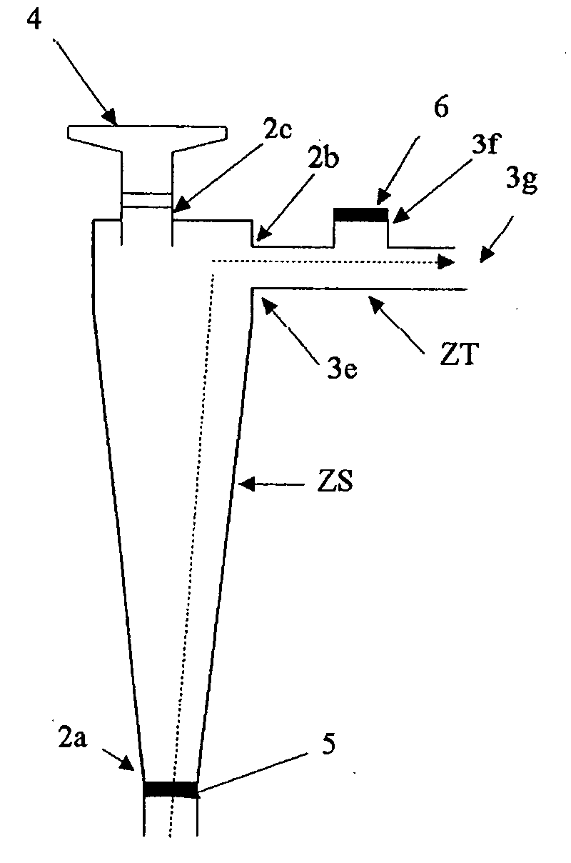
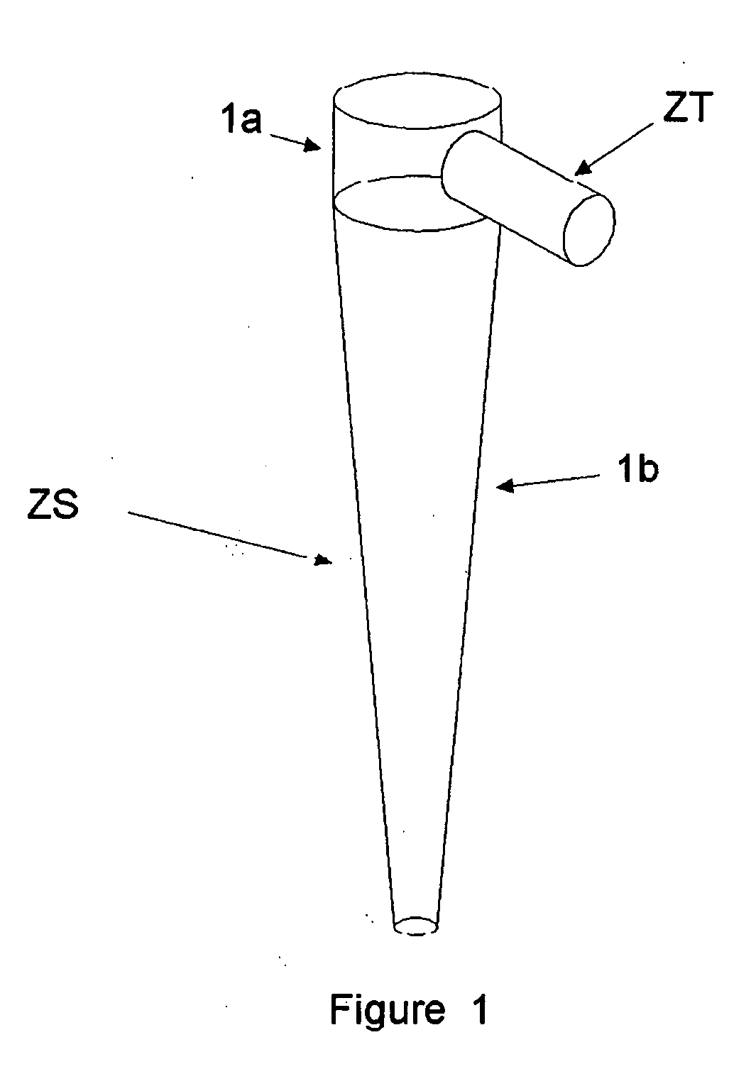
[0029] Medical aerosol generator systems comprise the aerosol generator itself and an interface between the aerosol generator and the patient. The aerosol generator is the source from which the aerosol is generated. The patient / aerosol generator interface is used to transport the aerosol from the generator to the patient (e.g. mask, mouthpiece, nosepiece, mechanical ventilator circuit, intubation catheter, tracheal catheter, etc.). The invention relates to the intermediate area between the area where the aerosol is generated and the area where it is transported (ZT) to the patient. This intermediate area is referred to as the “storage area” (ZS) (FIG. 1).

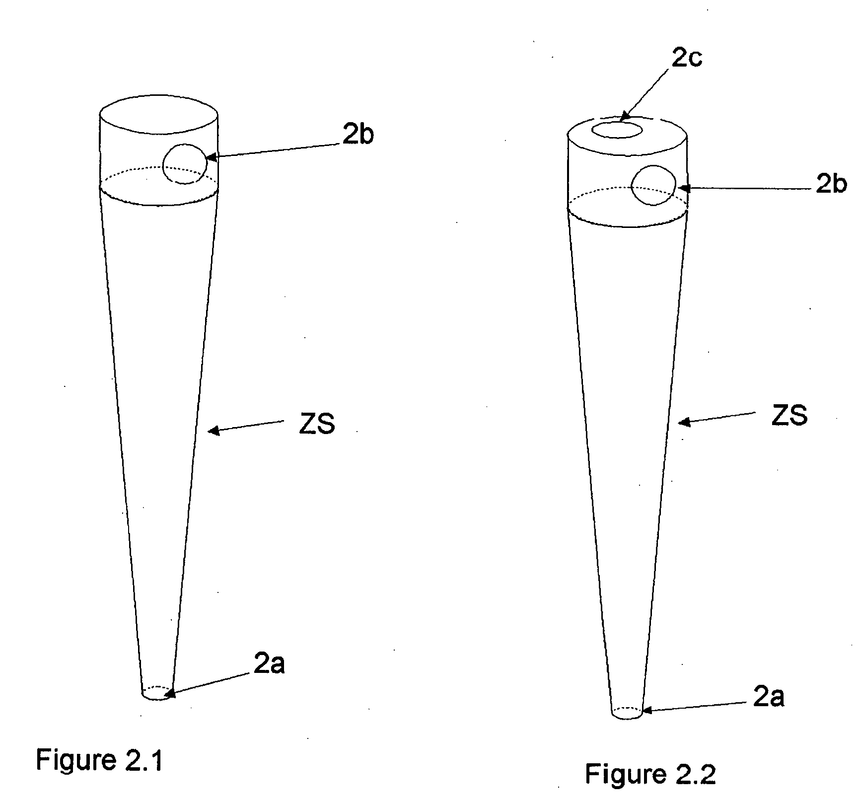
[0030] This area can be physically represented by the aerosol transfer device. This aerosol transfer device, referred to in its entirety as (ZS) is intended to receive aerosol generated by the aerosol generator and then, via the patient / aerosol generator interface, to transport it out of the aerosol generator system. This aerosol t...


PUM


Abstract

An aerosol transfer device for medical aerosol generators comprises an additional shaped element located in a vertical plane constituting an aerosol storage area. The additional element being designed with a first opening allowing movement of air from outside the storage area into the latter and being located on an upper or lower horizontal surface of the element in order to ensure vertical entry of air into the element, a second opening opposite said first opening allowing the escape of aerosol and a third opening for spraying aerosol into the storage area in the vertical plane of the storage area and in axial alignment with the first opening. The additional element has a minimum height of 6 cm and allows dispersion of the sprayed aerosol throughout the storage area without recycling the aerosol deposited on the walls of the storage area. The storage area is located between the aerosol generator source and the patient interface and allows, by means of a transport area, aerosol transport to the patient. The device does not include any valve on the path the aerosol takes from the storage area to the patient.

Description

BACKGROUND OF THE INVENTION [0001] The present invention relates to the technical field of medical aerosol generator systems. [0002] The purpose of medical aerosol generator systems is to convert a medicated liquid or powder into aerosol form so that it can be administered to the airways of the respiratory tract. [0003] There are various commercially available medical aerosol generator systems in the form of pneumatically controlled, ultrasonic and vibrating-membrane devices in particular, as well as pressurised canisters with a metering valve. [0004] The Applicant is one of the leading firms that manufacture and market this type of device. Despite all the research efforts devoted to these devices (generators, nebulisers and pressurised canisters), the various published studies on this subject all agree and confirm that a large proportion of the dispensed aerosol is lost and wasted rather than being used for the desired therapeutic treatment. Authors and manufacturers alike estimate...

Claims


Application Information

Patent Timeline
IPC IPC(8): A61M11/00A61M15/00
CPCA61M11/005A61M15/0085A61M15/0086A61M15/009A61M15/0015A61M15/0018
Inventor MASSARDIER, MICHELVECELLIO-NONE, LAURENTCHANTREL, GILLES
Owner LA DIFFUSION TECHN FR
Why Eureka
Try Eureka