
Systems and methods for dispensing fluid

a technology of fluid dispensing system and fluid dispensing method, which is applied in the direction of liquid dispensing, liquid transferring device, packaging, etc., can solve the problems of etc., and achieve the effect of reducing the risk of contaminating the valve, reducing health and mechanical difficulties, and simplifying the number of valves

Inactive Publication Date: 2006-06-29
BRIM ERIC +2
View PDF52 Cites 38 Cited by
  • Summary
  • Abstract
  • Description
  • Claims
  • Application Information

AI Technical Summary

Benefits of technology

[0014] The present invention relates generally to a mixing and dispensing mechanism. In one exemplary embodiment, the present invention pertains to the alcohol industry, specifically producing and distributing alcoholic drinks, even though it is not limited to this industry. The systems and methods according to the present invention may be applied to any other industry that could benefit from an automated mixing and dispensing systems and methods. In other words, the exemplary mixing and dispensing systems and methods according to the present have residential and commercial purposes. The residential apparatus may dispense a combination of fluids, such as organic alcohols, liquor, spirits, juices, and carbonated beverages, as a command from the user. In a commercial environment, the apparatus performs the same function, and keeps track of volumes of fluids dispensed. This type of apparatus creates close control over volumes of fluids the apparatus combines into drinks. The reduction in alcoholic waste or elimination of inconsistencies from the professionals is a potentially large economic gain. Another advantage of the present invention is the simple ability to track government monitored substances. This is a benefit to comply with government regulations around distributing alcohol. The ability to produce a volume of high-quality beverages with ease is important for commercial and economical success of the present invention. For example, if a bar makes a particularly popular drink, then that drink may be consistently made by programming the device with a proper combination of mixtures.
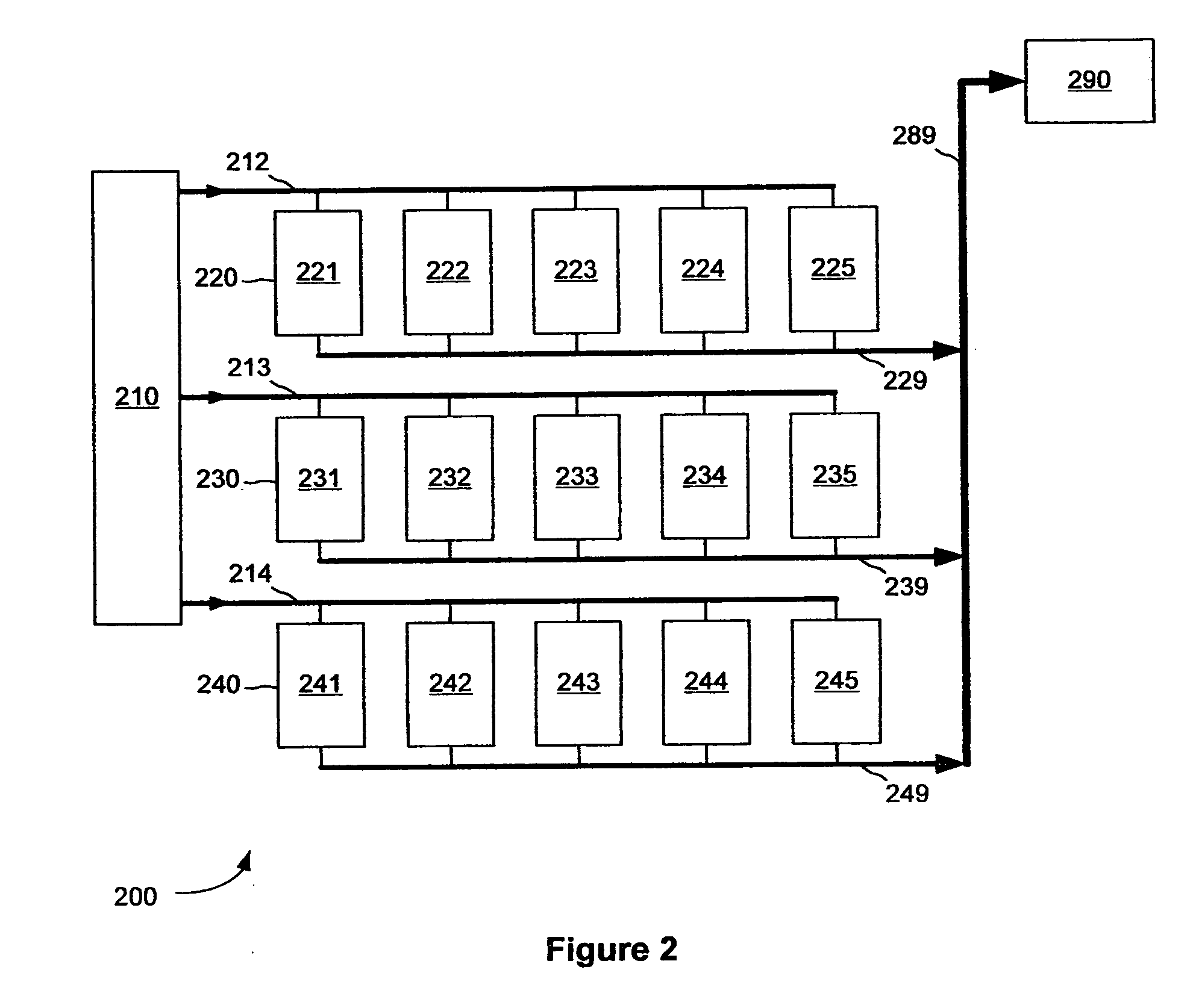
[0015] An exemplary embodiment comprises a set of reservoirs, with each reservoir containing a single valve on the pressurizing fluid side. This embodiment uses pressure versus time relationships to control volume flow as opposed to use of multiple valves per reservoir. This exemplary embodiment is just as effective as conventional systems, but without the additional costs for the extra mechanical elements. Also, by not having the discharge fluid come into contact with the valve mechanism, there is a decreased risk of contaminating the valves, thereby reducing health and mechanical difficulties. The advantage of the reduction and simplifying of the number of valves makes exemplary embodiments of the present invention cheaper, just as efficient, and easier to maintain. This argument applies to all conventional systems and methods with fluid being pumped by pressure.
[0016] In a broad sense, the present invention provides a system for mixing and distributing fluids. In one application of the present invention, the fluids are consumable, mass-producible fluids, such as organic alcohols, liquors, spirits, and any fluid that can be mixed with the consumable alcohols, liquors, and spirits, such as water (plain or carbonated), juices, and sodas. In this particular application, the present invention provides mixing and distributing of the fluids in order to produce a final beverage selected by the user.
[0017] The plurality of reservoirs, in accordance with an exemplary embodiment of the present invention, includes cylindrical tubes. The tubes are large enough in diameter and height to hold a specific amount of fluid. The cylinders are preferably made of stainless steel. In other aspects, the shape of the reservoir is not restricted to a cylinder, and can have a cross-section represented by any geometric shape, such as a square, rectangle, triangle, pentagon, hexagon, octagon, oval, ellipse, etc. Preferably, the reservoir is generally cylindrical to aid in cleaning. Preferably, the reservoir has a bottom surface that is generally conical to aid in removal of small volumes of liquid from the reservoir. The reservoirs can be made of any material that is able to withstand the pressure exerted upon it by the system without causing expansion or being altered or altering the fluid stored in the reservoir. Exemplary materials include, but are not limited to, plastic, glass, and other metals, or combinations thereof. In the present application, there is a capped-opening in the top of each reservoir to refill the fluid. In each reservoir, the supply gas enters at the top, and the fluid is drawn out of the bottom.
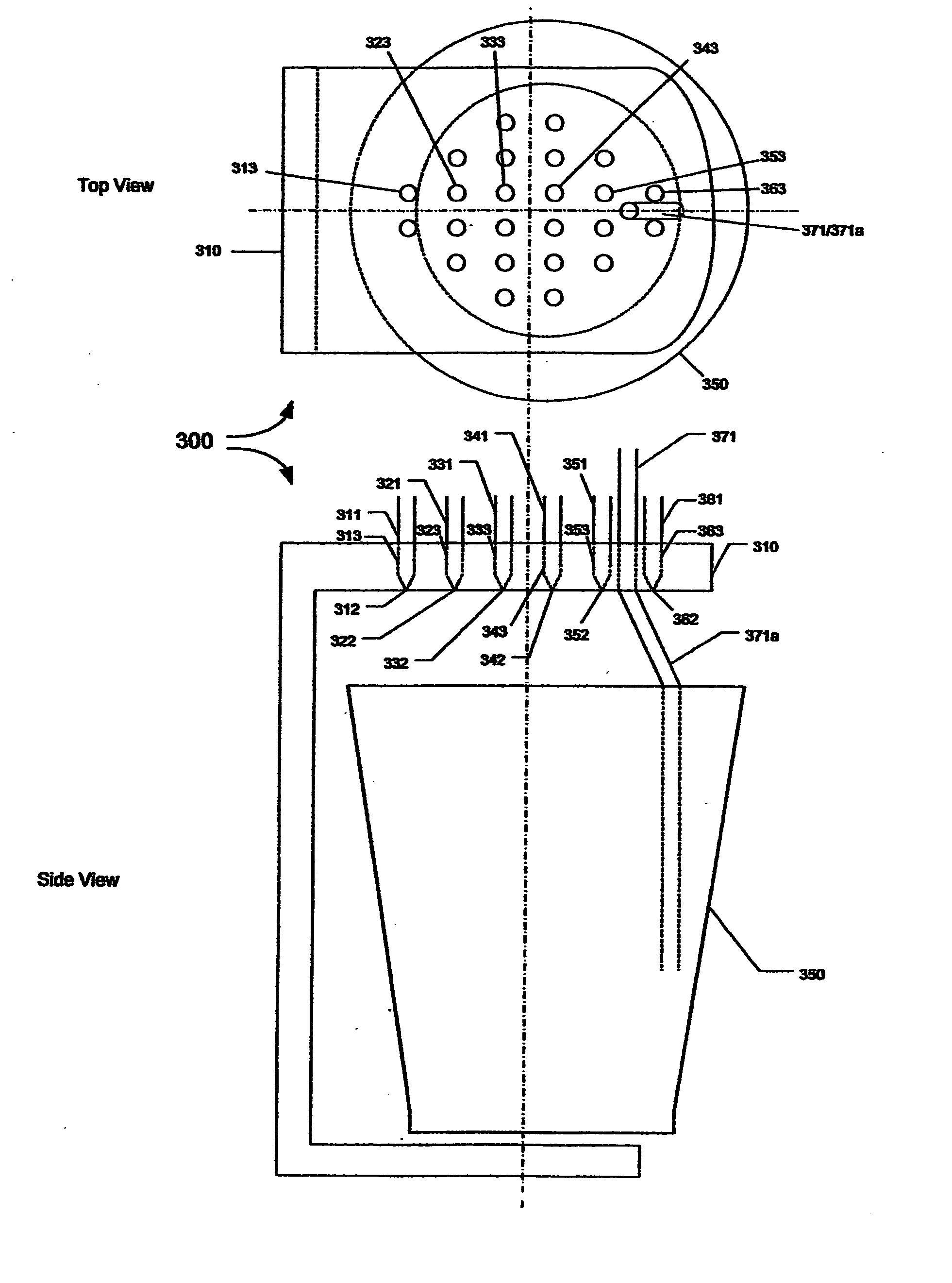
[0018] The mixing apparatus is a single common application to the plurality of reservoirs. The mixing apparatus is implemented in many ways. The mixing apparatus can use gravity or the force and angle of dispensing from the nozzles and / or the shape of the final container (e.g., cup or glass) for the mixed drink, to mix the fluids. The mixing apparatus can also use the supply gas to aerate the fluid, or if mixing is not necessary, the mixing process is then just used to combine the fluids into one location.

Problems solved by technology

Also, by not having the discharge fluid come into contact with the valve mechanism, there is a decreased risk of contaminating the valves, thereby reducing health and mechanical difficulties.

Method used


Image

  • Systems and methods for dispensing fluid
  • Systems and methods for dispensing fluid
  • Systems and methods for dispensing fluid

Examples


Embodiment Construction

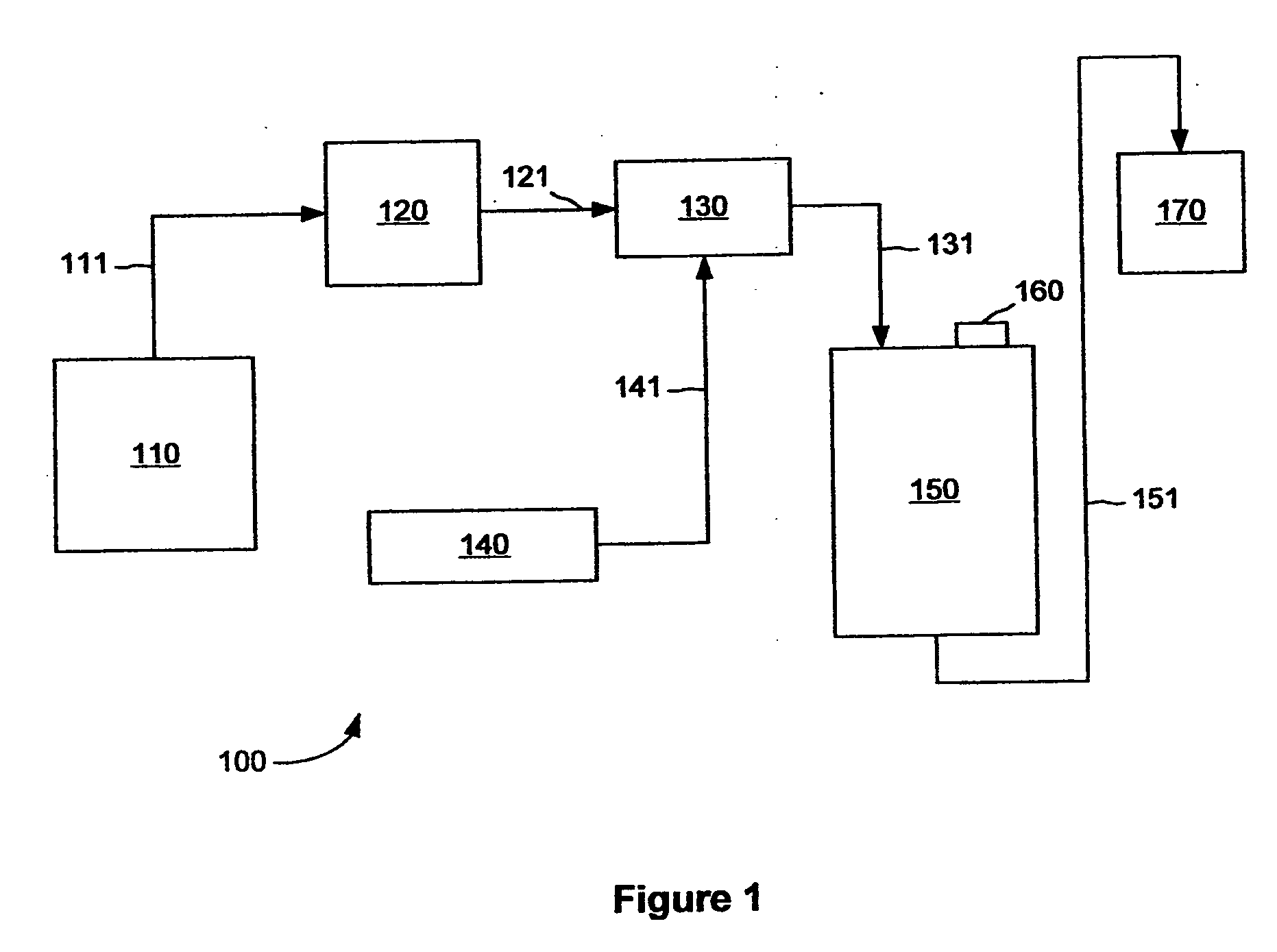
[0027] The present invention is a mixing and dispensing apparatus made of multiple components. These components include control gas, plurality of control valves, plurality of reservoirs, a mixing apparatus, and a control system. The control gas provides a regulated gas to a single manifold of control valves. This control gas for this particular application is any inert gas with no known harmful effects on humans, such as carbon dioxide, nitrogen, and air. In other applications where human consumption is not an end result, any gas capable of applying pressure to the fluid without interference may be substituted. Implementing a pressurizing fluid in a bladder, or any other means to separate two fluids, to apply a pressure to the fluid in the reservoir may also be used as a control gas. An exemplary but non-limiting application of the systems and methods according to the present invention is to make and deliver mixed drinks, such as those provided at bars or restaurants.

[0028] The con...


PUM


Abstract

The present invention provides an automatic mixing and dispensing device that includes a plurality of storage reservoirs for various liquids interposed between a source of pressurized gas and a mixing and dispensing unit. The device further includes a final receiving area into which the liquids can be dispensed. The invention also provides a method for storing and delivering fluids to a centralized mixing and dispensing unit, which can include dispensing a mixed beverage to a final container, such as a cup. The method includes applying pressure to a reservoir tank holding a desired liquid, thus forcing the liquid from the tank into the mixing and dispensing unit. The amount of time that the pressure is applied to the reservoir tank correlates to a specific amount of volume delivered. The method can be accomplished using a computer.

Description

CROSS-REFERENCE TO RELATED APPLICATIONS [0001] This application relies on and claims the benefit of the filing date of U.S. Provisional patent application No. 60 / 628,775, filed 18 November 2004, the entire disclosure of which is hereby incorporated herein by reference.BACKGROUND OF THE INVENTION [0002] 1. Field of the Invention [0003] The present invention relates to the field of dispensing of fluids. More specifically, it relates to systems and devices that mix and dispense multiple fluids based on pre-set recipes. [0004] 2. Discussion of Related Art [0005] Automated mixing and dispensing machines have been proposed as a solution to various problems encountered in the food and drink industry. For example, they have been proposed as a solution to wasteful and inaccurate dispensing of alcohol in bars and other establishments that serve alcoholic drinks. They have also been proposed as a solution to inconsistencies in mixing of various drinks from establishment to establishment, and t...

Claims


Application Information

Patent Timeline
Patent Type & Authority Applications(United States)
IPC IPC(8): B67D5/56B67D7/74
CPCB67D1/0021B67D1/0052B67D1/04
Inventor BRIM, ERICTINDALL, SCOTTKALANICK, MICHAEL F. JR.
Owner BRIM ERIC
Learn More