
Fuel cell system

a fuel cell and system technology, applied in the field of fuel cell systems, can solve the problems of difficult to completely equalize the power generation performance and conditions of all the cells, the tolerable range of power generation cannot be flexibly changed depending on the cell voltage reduction factor, and the inability to flexibly change the tolerable range of power generation. the effect of simplifying the control of the cell voltag

Inactive Publication Date: 2010-03-18
TOYOTA JIDOSHA KK
View PDF3 Cites 28 Cited by
  • Summary
  • Abstract
  • Description
  • Claims
  • Application Information

AI Technical Summary

Benefits of technology

The present invention provides a fuel cell system that can flexibly change the tolerable range of power generation depending on the operation conditions. The system can determine whether the cell voltage reduction factor is the fuel gas shortage or the oxidation gas shortage and manage the cell voltage accordingly. This allows for proper operation of the fuel cell even when certain conditions are met. The system can also set a lower voltage limit to prevent a decrease in output voltage, and can recover the cell voltage by increasing the supply of fuel gas or oxidation gas or limiting the output current. The system can also set a lower voltage limit based on the fuel gas shortage or the oxidation gas shortage to flexibly manage the cell voltage.

Problems solved by technology

However, with the conventional operation scheme, since the lower voltage limit has a predetermined fixed value, a tolerable range of power generation cannot be flexibly changed depending on a cell voltage reduction factor.
Disadvantageously, the tolerable range of power generation is fixed.
Furthermore, if a fuel cell stack made up of a plurality of cells stacked in series is operated, completely equalizing the power generation performance and conditions of all the cells is difficult.
When operation conditions are degraded owing to a decrease in proton conductivity caused by a dry-up phenomenon, the shortage of the supply of the reaction gas, or the like, the cell voltage decreases in cells with low power generation performance or in improper conditions.
Among the cell voltage reduction factors, a shortage of the fuel gas may electrochemically damage the fuel cell stack.
However, with the conventional scheme, determining whether the cell voltage reduction factor is the fuel gas shortage or the oxidation gas shortage is difficult.
Thus, when a decrease in cell voltage is detected, output is equally limited even if the cell voltage reduction factor is the oxidation gas shortage.
As a result, drivability may be degraded.

Method used


Image

  • Fuel cell system
  • Fuel cell system
  • Fuel cell system

Examples


embodiment 1

[0059]Now, cell voltage management according to Embodiment 1 will be outlined.

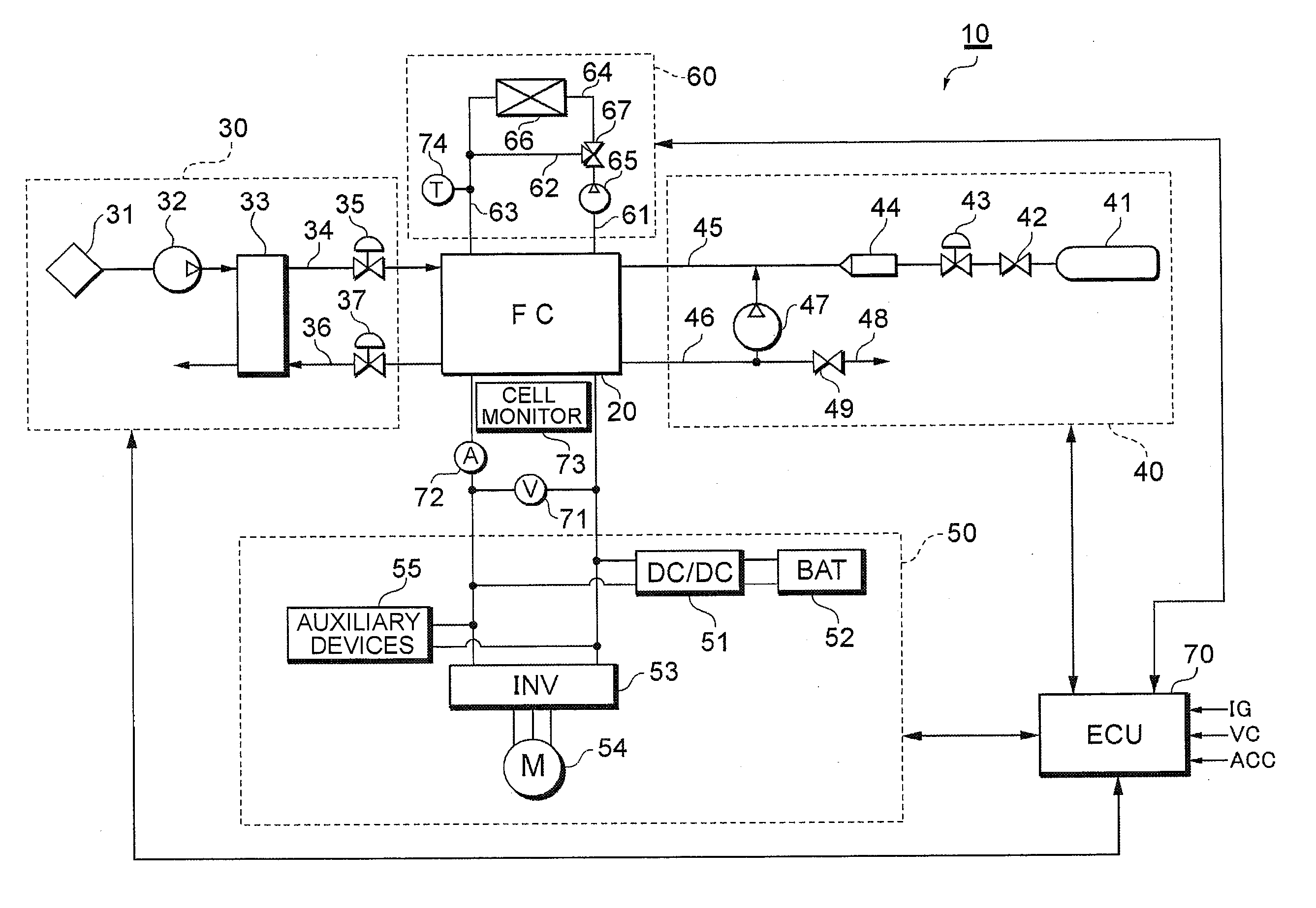
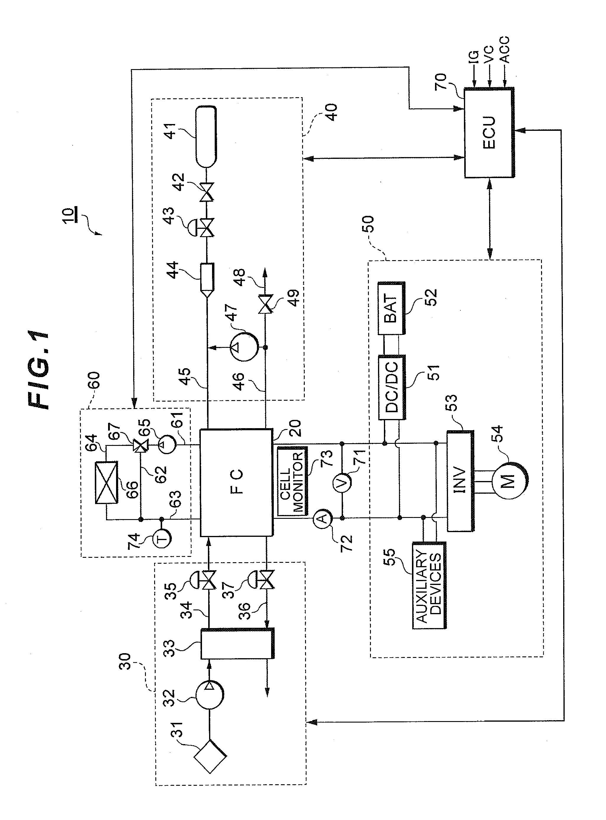
[0060]The controller 70 performs operation control while limiting the operation so as to prevent the cell voltage from decreasing below a lower voltage limit Vth. The controller 70 changes conditions for the operation limitation depending on the operation condition of the fuel cell stack 20. The operation condition is a concept collectively referring to physical quantities relating to the cell voltage reduction factors (a shortage of the supplied reaction gas, a decrease in stack temperature, and the like). The conditions for the operation limitation refer to conditions for limiting the cell operation (for example, the lower voltage limit Vth, indicating the lower limit of the power generation tolerable range). The severity of the conditions for the operation limitation is desirably reduced consistently with the stack temperature. For example, the lower voltage limit Vth for low-temperature starting is des...

embodiment 2

[0083]Cell voltage management in a low-temperature environment according to Embodiment 2 will be described.

[0084]FIG. 6 is a flowchart showing a low-temperature starting routine. The routine is invoked during a low-efficiency operation and executed by the controller 70. The low-efficiency operation refers to an operation of controlling the supply amount of the reaction gas supplied to the fuel cell stack 20 with an air stoichiometry set to about 1.0 so as to increase a power loss for operation at a low power generation efficiency. The air stoichiometry refers to an oxygen excess rate, and indicates how excess the supplied oxygen is with respect to the amount of oxygen required for adequate reaction with hydrogen. Performing the low-efficiency operation with the air stoichiometry set to a small value increases concentration overvoltage and thus a heat loss (power loss) contained in energy obtained through the reaction between hydrogen and oxygen. The low-efficiency operation is utili...

embodiment 3

[0097]Now, cell voltage management according to Embodiment 3 will be described. The cell voltage management described below is assumed to be used mainly for the normal operation. However, owing to the lack of the temperature limitation, the cell voltage management can in principle be applied to the low temperature environment (for example, during the low-efficiency operation).

(1) Cell Voltage Management Based on the Cell Electrode Potential

[0098]FIG. 7 shows a variation in electrode potential, that is, the electrode potentials measured during the starting and the normal operation and when the oxidation gas is in shortage and when the fuel gas is in shortage. During the starting, the output voltage from the fuel cell stack 20 is set to an open end voltage, resulting in a zero output current. At this time, a cathode potential CA1 exhibits no voltage drop caused by a DC resistance component and is set to the open end voltage. Furthermore, an anode potential AN1 remains zero. A cell vol...


PUM

PropertyMeasurementUnit
voltageaaaaaaaaaa
output voltageaaaaaaaaaa
temperatureaaaaaaaaaa

Abstract

A fuel cell system determines whether an operation condition of a fuel cell corresponds to a fuel gas shortage or an oxidation gas shortage. Upon determining that the fuel gas is in shortage, the system sets a lower voltage limit to be higher than that set when the system determines that the oxidation gas is in shortage. The system further controls an output voltage from the fuel cell so as to prevent output voltage from the fuel cell from decreasing below the lower voltage limit.

Description

TECHNICAL FIELD[0001]The present invention relates to a fuel cell system including a fuel cell that receives a supply of a fuel gas and an oxidation gas to generate power.BACKGROUND ART[0002]A fuel cell stack has a stack structure with a plurality of cells stacked in series. Each of the cells includes a membrane-electrode assembly with an anode located on one surface of an electrolytic membrane and a cathode located on the other surface thereof. Supplying a fuel gas and an oxidation gas to the membrane-electrode assembly induces an elecrtrochemical reaction. Thus, chemical energy is converted into electric energy. In particular, a solid polyelectrolyte fuel stack using a solid polymer film as an electrolyte requires reduced costs, is easy to make compact, and offers a high power density. The solid polyelectrolyte fuel stack is thus expected to be used as a vehicle-mounted power source.[0003]To operate a fuel cell system, moisture inside the fuel cell stack and the temperature of the...

Claims


Application Information

Patent Timeline
Patent Type & Authority Applications(United States)
IPC IPC(8): H01M8/04
CPCH01M8/04559H01M8/04589H01M8/04753Y02E60/50H01M8/0491H01M8/04955H01M8/04992H01M8/0488
Inventor HAMADA, HITOSHIKUBO, HIDEKINOTO, HIRONORI
Owner TOYOTA JIDOSHA KK
Learn More