Decorative coverage and snow melting system

a technology which is applied in the field of decorative coverage and snow melting system, can solve the problems of not being able to prevent snow accumulation, removing snow, and pushing snow further away from the cleaned area, and achieve the effect of preventing snow accumulation

Inactive Publication Date: 2006-06-29
HEUMANN NIR
View PDF4 Cites 5 Cited by
  • Summary
  • Abstract
  • Description
  • Claims
  • Application Information

AI Technical Summary

Benefits of technology

[0023] A modular coverage system for covering an area of desired shape and size with the purpose of heating the said area in order to prevent snow accumulation or to melt down accumulated snow or for decoration, protection and comfort.

Problems solved by technology

A further disadvantage of these devices is that they neither prevent the snow accumulating nor remove it but rather push it further away from the cleaned area.
The electric snow melting systems known in the art are however characterized by diverse disadvantages that need to be overcome before an efficient and convenient to install and to use system can be achieved while keeping production and installation costs at a low level.
Thus embedded snow melting systems need to be installed underneath the concrete or asphalt or any other paving material, such underground installation involving many complications and necessitating the hiring of a constructor with heavy machinery equipment.
This is the most common solution in the market as to date even though it requires highly time consuming and costly planning, contracting, building and installation procedures.
It is a further disadvantage of these systems that installation may give rise to various technical problems such as cable dislocation during asphalt pouring and access for maintenance is complicated.
Embedded roof coverage melting systems are similarly costly, time consuming and necessitating professional help for maintenance while external systems for roofs are characterized by visible cables that create an esthetically imperfect look while also causing accumulation of dry leaves and dirt.
At the same time these systems have an insufficient melting, effect such that a few inches away from the cables snow remains unaffected.
The procedure of installing an embedded roof coverage melting system is made even more expensive and lengthy due to the fact that it involves replacing or removing and reinstalling the roof tiles.
These mats come in predefined size and shape and do not suit non-straight shapes.
Because they are not firm they are unsuitable for covering driveways.
It is impossible to use such mats to cover large areas and additional equipment is needed for securing them to the ground.
It is a serious disadvantage of these mats that in the event of malfunctioning or damage in a small area, the product needs to be completely replaced.
This type of snow melting apparatus necessitates construction by a professional team and does not allow full modularity in all directions.
Such systems cannot be used to cover extensive surfaces of different shapes and they have the additional drawback that due to a linear conducting system a failure in one modular element disconnects the whole line of elements extending beyond it.
This snow melting device has the drawbacks of necessitating separate electrical connecting means such as male connectors and mechanical attachment means such as plates and screws, resulting in a product design that is cluttered and tedious to use.
It is a further drawback of this device that the electrical connecting means can only be introduced horizontally through the length and width edges of the modular plates whereby the covering of large areas with plates connected on all four sides becomes complicated and replacement of defective plates is hardly possible.

Method used


Image

  • Decorative coverage and snow melting system
  • Decorative coverage and snow melting system
  • Decorative coverage and snow melting system

Examples


Embodiment Construction

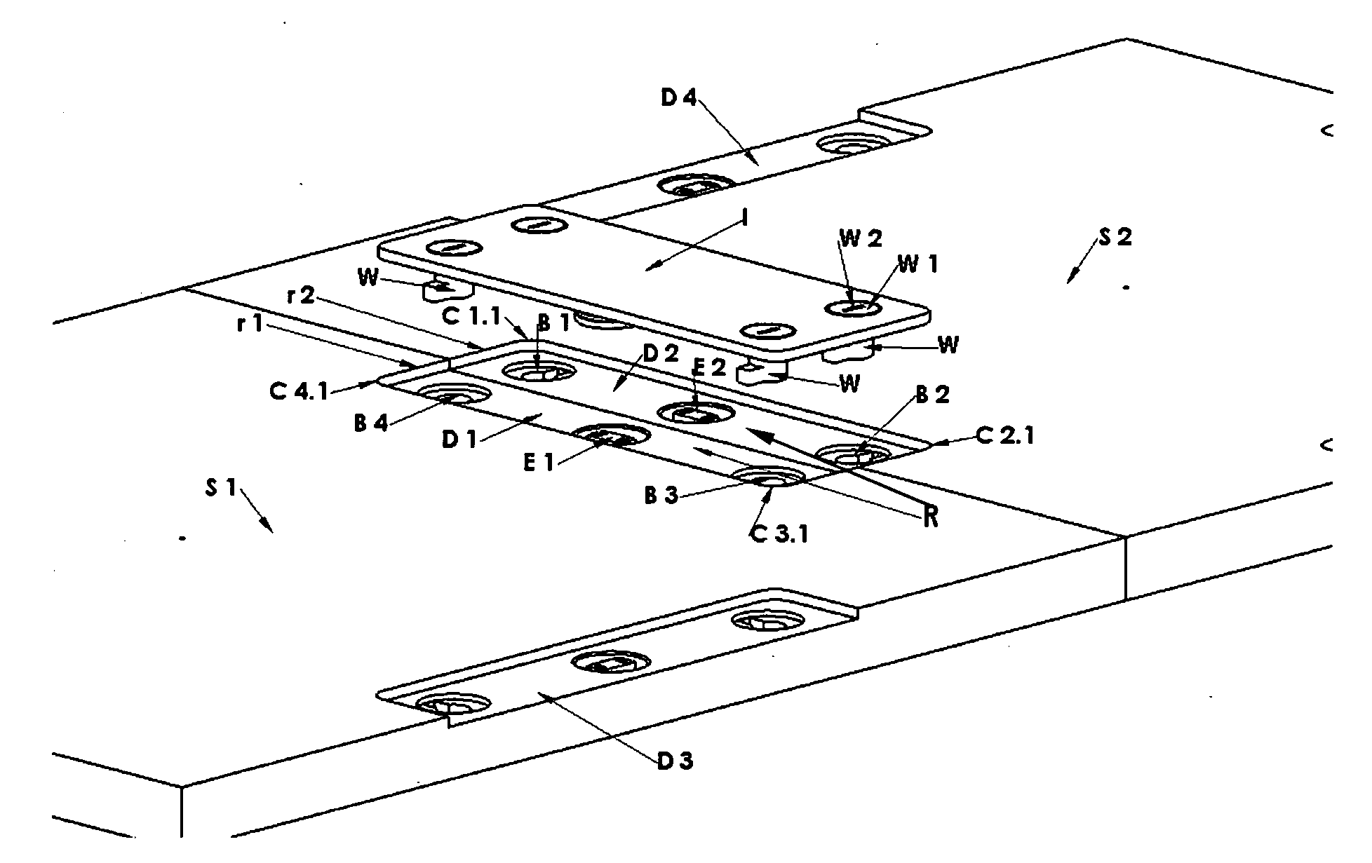
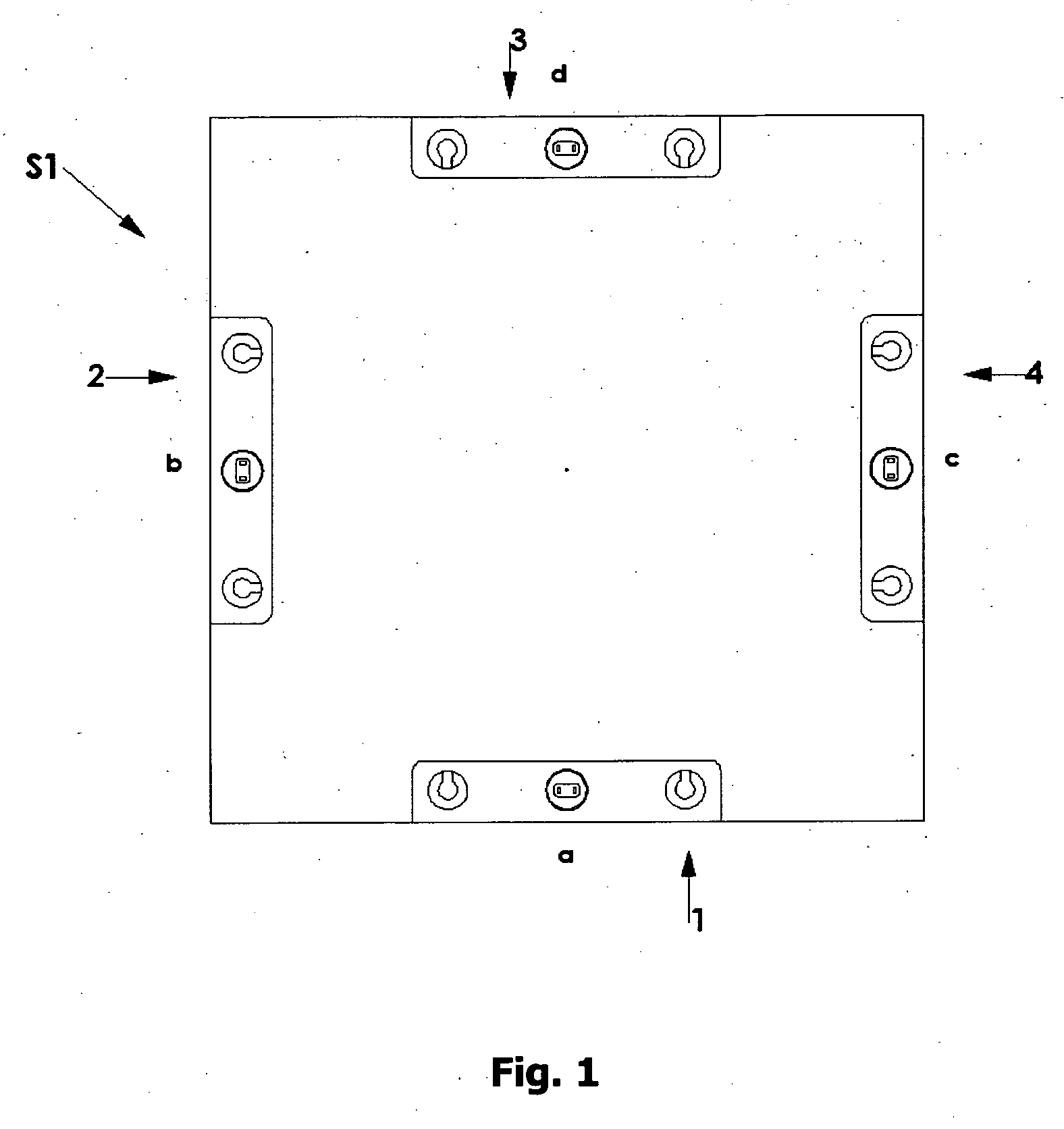
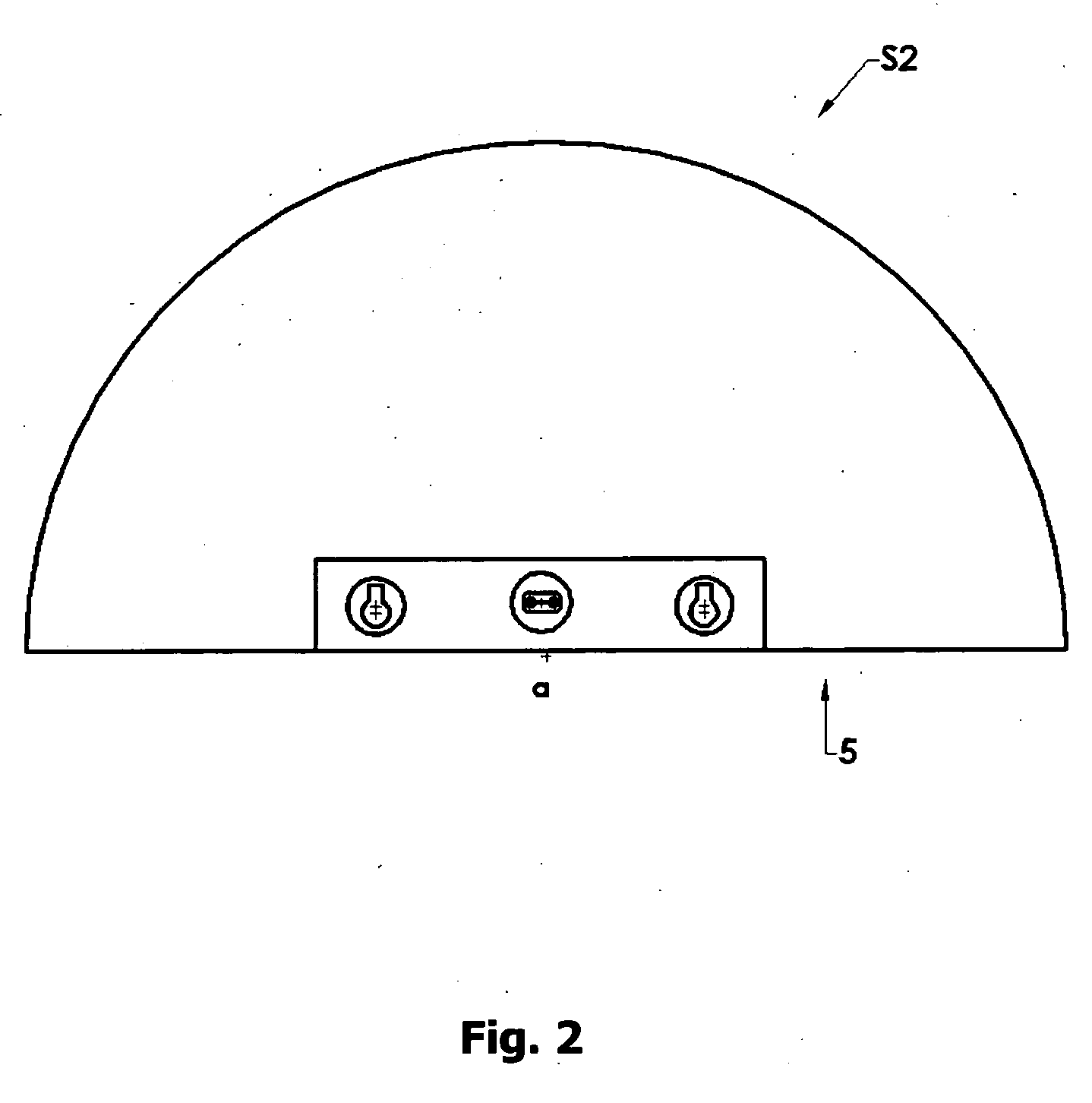
[0047] The present invention provides a modular coverage system that is suitable for covering both large and small areas and may be used for covering roofs, driveways, sidewalks, stairs or indoor or outdoor areas of any shape such as porches, entrance areas etc. The modular coverage system of the invention may comprise electric conducting and heating means such as electric wires and heating wires for the purpose of melting snow or preventing the accumulation of snow by heating the ground covered by the modular coverage system.

[0048] In accordance with another aspect of the invention the modular coverage system may be made without any electric conducting and heating means and used for decorative or protective purposes.

[0049] The inventive modular coverage system is made of surface units available in different geometrical shapes and in a variety of patterns, materials, sizes, textures and colors thus enabling the construction of a decorative coverage according to the user's individu...


PUM


Abstract

A modular coverage system for covering an area of desired shape and size with the purpose of heating the said area in order to prevent snow accumulation or to melt down accumulated snow or for decoration, protection and comfort, comprising a plurality of generally planar surface units suitable to be laid out adjacent to each other that may be made with different decorative patterns. In snow melting systems electric conducting and heating means are located inside the surface unit. Along the outline of the surface unit recessed docking station means are provided in the areas that are designed to be adjacent to the outline of a neighboring surface unit. Each docking station means comprises electrical connection means and one or more mechanical engagement means. Units are interconnected by removable integral connecting plates with electrical connection means and mechanical engagement means inserted from above and received in the docking station areas. A removable docking station cover panel is used to cover docking station means that remain unattached, and keep them watertight. An electrical docking station cover panel with electrical connection means may be attached to a docking station means in a surface unit positioned at any convenient location within the snow melting system to connect the snow melting system to a power source. The electric means in the surface units are connected in a parallel circuit such that electricity supply persists in the event of failure in one of the surface units. The modular coverage system may be made without electrical and heating means to be used for decorative and protective purposes.

Description

BACKGROUND OF THE INVENTION [0001] The need to keep outdoor areas, driveways, sidewalks and stairs around houses or business premises free of snow while eliminating the need for repetitive heavy manual work gave rise to a large variety of products such as the car snowplow, home snow throwers and similar mechanical solutions that at the end of the day still require time consuming handling and operating. A further disadvantage of these devices is that they neither prevent the snow accumulating nor remove it but rather push it further away from the cleaned area. [0002] A much more advanced and work saving solution was achieved by the introduction of electrically operated snow melting systems. These systems are intended to melt away the snow without the need for exerting further efforts either manually or mechanically and they will perform the task of keeping a driveway, a road or a parking lot clean of snow or ice in the absence of the owner, thereby liberating him from the tedious eve...

Claims


Application Information

Patent Timeline
Patent Type & Authority Applications(United States)
IPC IPC(8): H05B3/00
CPCE01C11/265
Inventor HEUMANN, NIR
Owner HEUMANN NIR
Why Eureka
Try Eureka