Fuel cell metallic separator

a technology of metallic separators and fuel cells, applied in the direction of electrochemical generators, cell components, cell component details, etc., can solve the problems of complicated injection molding process and the method of manufacturing these plates

Active Publication Date: 2006-06-29
CELLCENTRIC GMBH & CO KG +1
View PDF10 Cites 62 Cited by
  • Summary
  • Abstract
  • Description
  • Claims
  • Application Information

AI Technical Summary

Problems solved by technology

Corrosion of metallic separator plates, more specifically around the communication ports for the fluid streams, is a concern in the operation of fuel cell systems.
The concern is the occurrence of a liquid short-circuit at the edges of the ports between adjacent fluid stream and the resultant electrolytic corrosion.
However, the selection of the proper coating material has proven to be a challenge as such material must also be suitable for the high temperature and the high relative humidity environment of fuel cell systems.
The method for manufacturing these plates, however, is complicated injection molding processes, as the elastomeric seals must form part of a separate step from the initial resin-forming step.

Method used


Image

  • Fuel cell metallic separator
  • Fuel cell metallic separator
  • Fuel cell metallic separator

Examples


Embodiment Construction

[0021] Many specific details of certain embodiments of the invention are set forth in the detailed description below, and illustrated in enclosed FIGS. 1 and 2, to provide a thorough understanding of such embodiments. One skilled in the art, however, will understand that the present invention may have additional embodiments, or may be practiced without several of the details described.

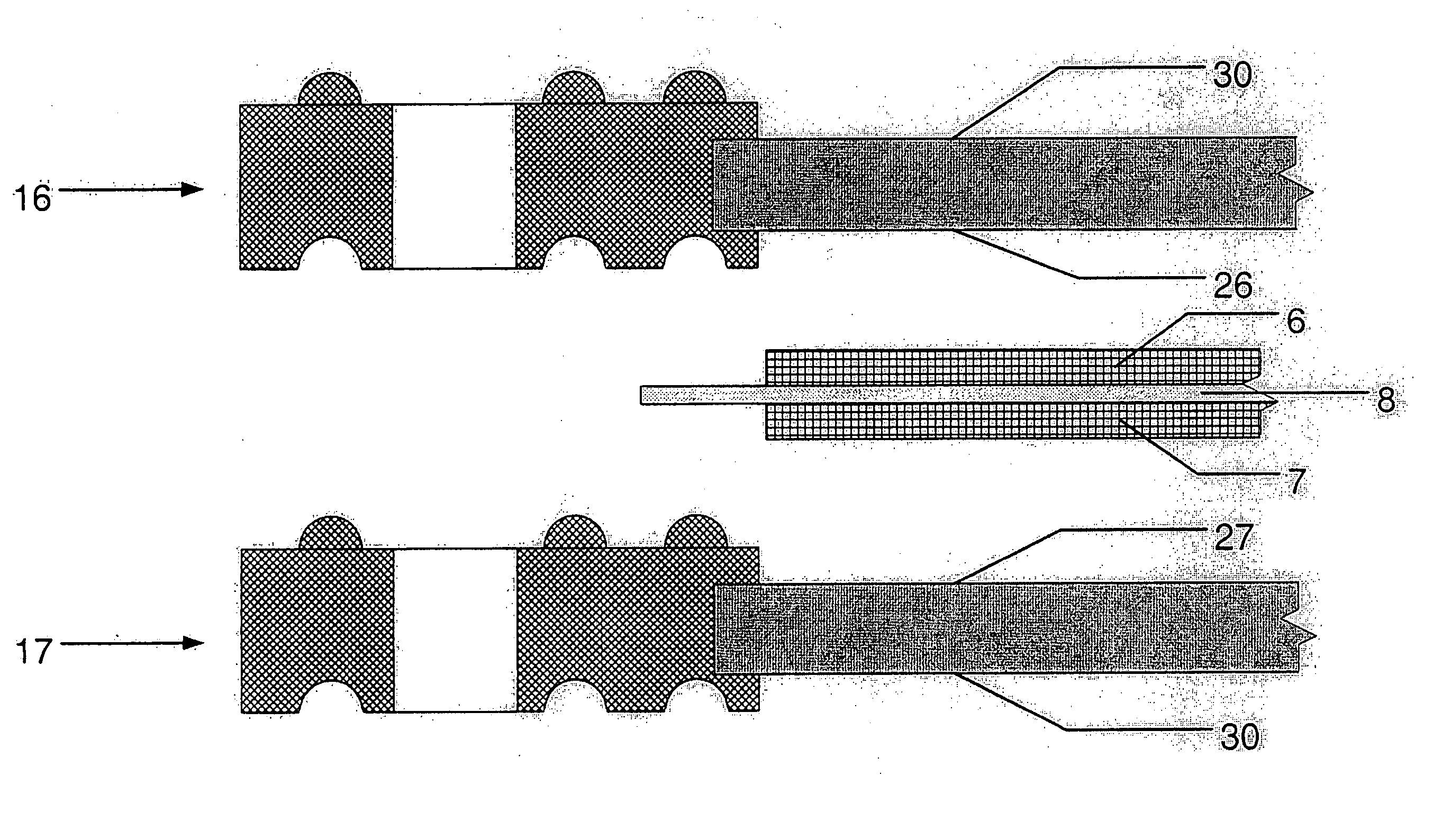
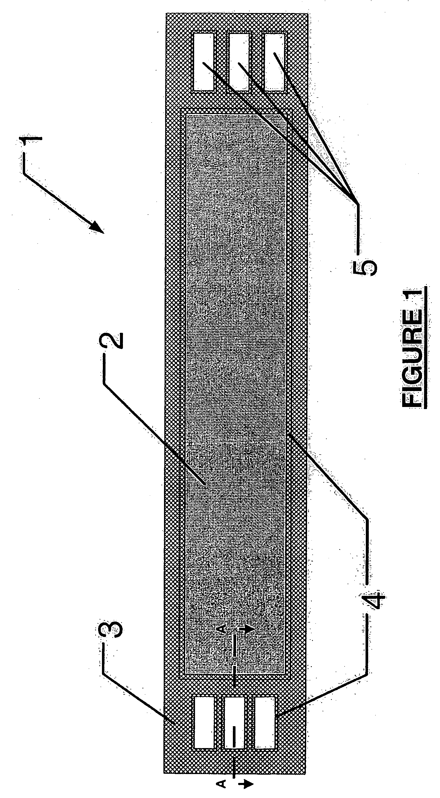
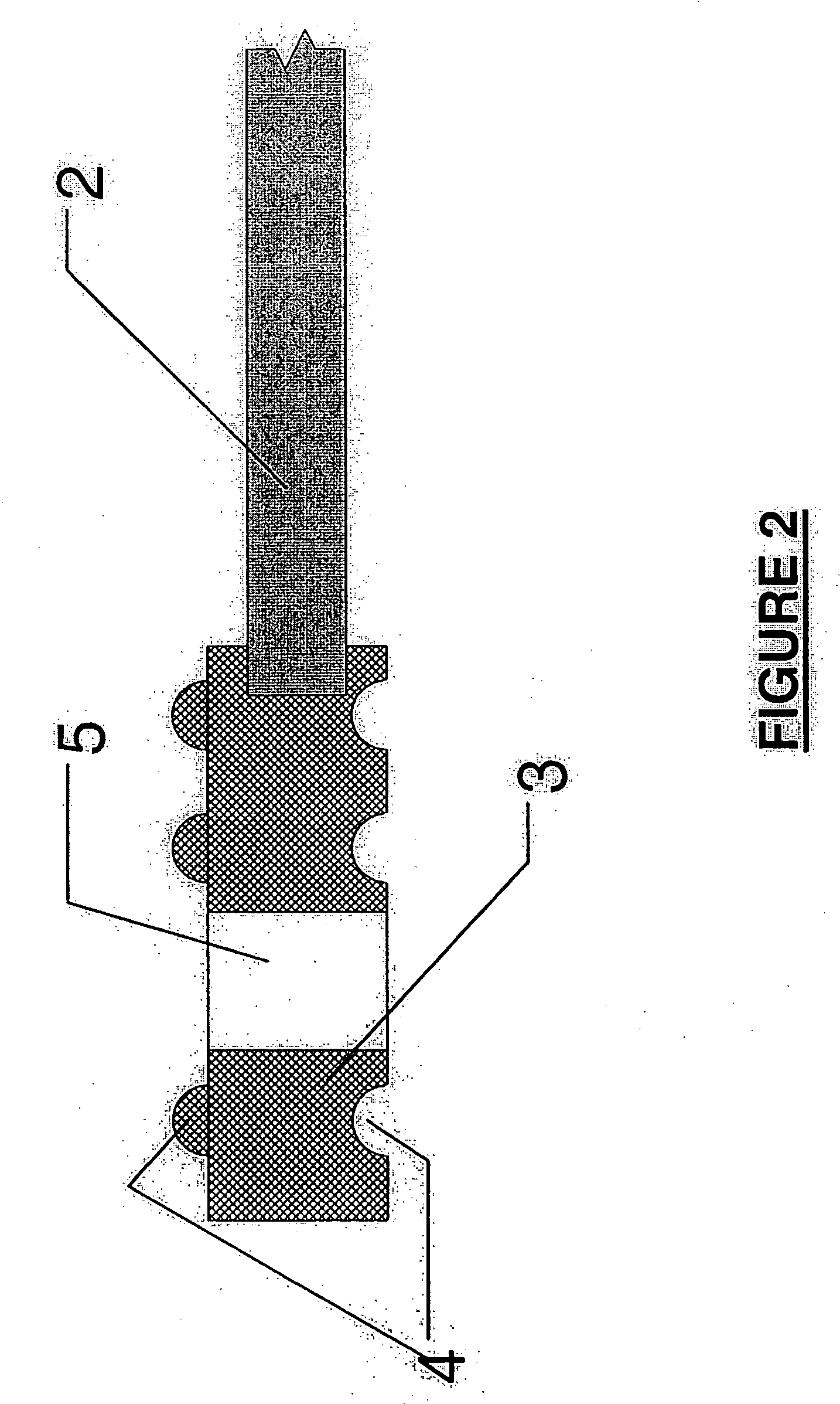
[0022] An embodiment of a fuel cell metallic separator pursuant to the invention is shown at FIG. 1. Fuel cell metallic separator 1 comprises a resin portion 3 integrally formed on edge portions of a metallic plate 2. Communication ports 5 are provided in resin portion 3 for allowing fuel, oxidant and coolant of a fuel cell to pass therethrough, and a rib portion 4 is provided on metallic plate 2 and resin portion 3 as an airtight seal. Rib portion 4 is described in more details below.

[0023] Fuel cell metallic separator 1 according to the invention is such as to constitute a partition wall between si...


PUM

PropertyMeasurementUnit
operating temperaturesaaaaaaaaaa
shapeaaaaaaaaaa
electric poweraaaaaaaaaa

Abstract

The invention provides a fuel cell metallic separator, wherein the metallic plate's edges include a resin portion comprising the communication ports. The resin portion around the communication ports is shaped so as to be capable of interlocking with a fuel cell stack component adjacently located in a fuel cell system. The invention also provides a resin portion capable of press fitting or thermal bonding with adjacent a fuel cell stack components.

Description

BACKGROUND OF THE INVENTION [0001] 1. Field of the Invention [0002] The present invention generally relates to fuel cell metallic separators and to methods for manufacturing such separators. [0003] 2. Description of the Related Art [0004] Electrochemical fuel cell assemblies convert reactants, namely fuel and oxidant, to generate electric power and reaction products. Electrochemical fuel cell assemblies generally employ an electrolyte disposed between two electrodes, namely a cathode and an anode. The electrodes generally each comprise a porous, electrically conductive sheet material and an electrocatalyst disposed at the interface between the electrolyte and the electrode layers to induce the desired electrochemical reactions. The location of the electrocatalyst generally defines the electrochemically active area. [0005] Solid polymer fuel cell assemblies typically employ a membrane electrode assembly (“MEA”) consisting of a solid polymer electrolyte, or ion exchange membrane, disp...

Claims


Application Information

Patent Timeline
Patent Type & Authority Applications(United States)
IPC IPC(8): H01M8/02B32B15/08H01M2/08
CPCH01M8/0206H01M8/0213H01M8/0221H01M8/0223H01M8/0276H01M8/0284H01M8/241Y02E60/50H01M8/0273Y10T428/31678
Inventor MACKINNON, SEAN M.ERICKSON, LYNN C.RASHID, AYESHAKIRBY, CHRISTOPHER T.
Owner CELLCENTRIC GMBH & CO KG
Why Eureka
Try Eureka