
Coated substrate assembly

a technology of coating substrates and assembly parts, which is applied in the direction of magnetic bodies, blood vessels, and therapy, can solve the problems of not providing a solution to the mri imaging of stents, the inability to study the blood flow in the area directly around the stents, and the difficulty in using mri with prior art stents

Inactive Publication Date: 2006-06-29
BIOPHAN TECH
View PDF3 Cites 83 Cited by
  • Summary
  • Abstract
  • Description
  • Claims
  • Application Information

AI Technical Summary

Problems solved by technology

Published United States patent application US 2004 / 0093075 discloses that, although magnetic resonance imaging (MRI) is widely used, there is a difficulty in using MRI with prior art stents because such stents distort the magnetic resonance images of blood vessels.
As a result, it was impossible to study the blood flow in the stents and the area directly around the stents for determining tissue response to different stents in the heart region.
Published United States patent application US 2004 / 0093075 does not provide a solution to the MRI imaging of stents that it broadly applicable to many prior art stents, and to other assemblies.

Method used


Image

  • Coated substrate assembly
  • Coated substrate assembly
  • Coated substrate assembly

Examples


Embodiment Construction

[0067] In the first part of this specification, a preferred seed assembly will be described. Thereafter, other embodiments of the invention will be described.

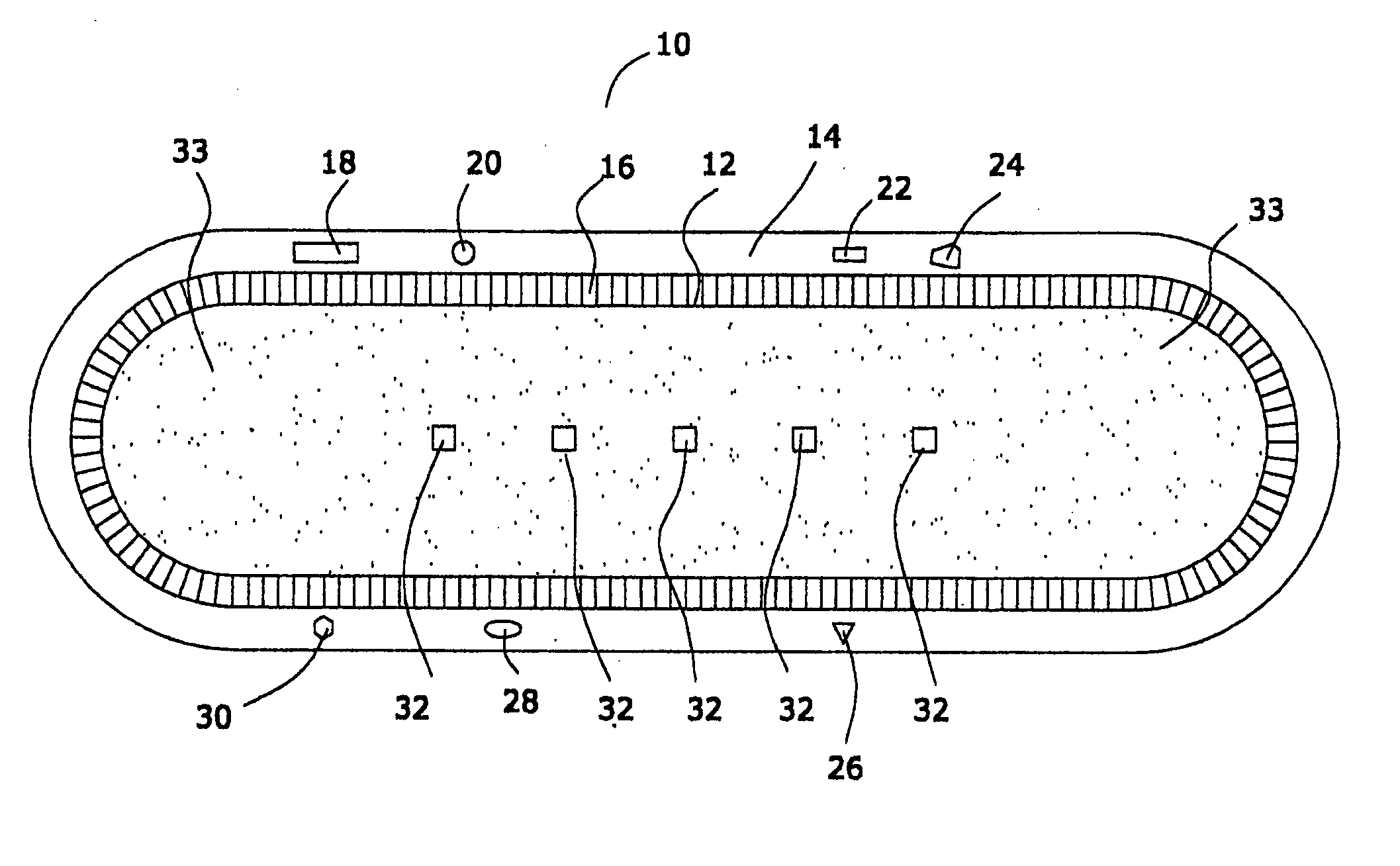
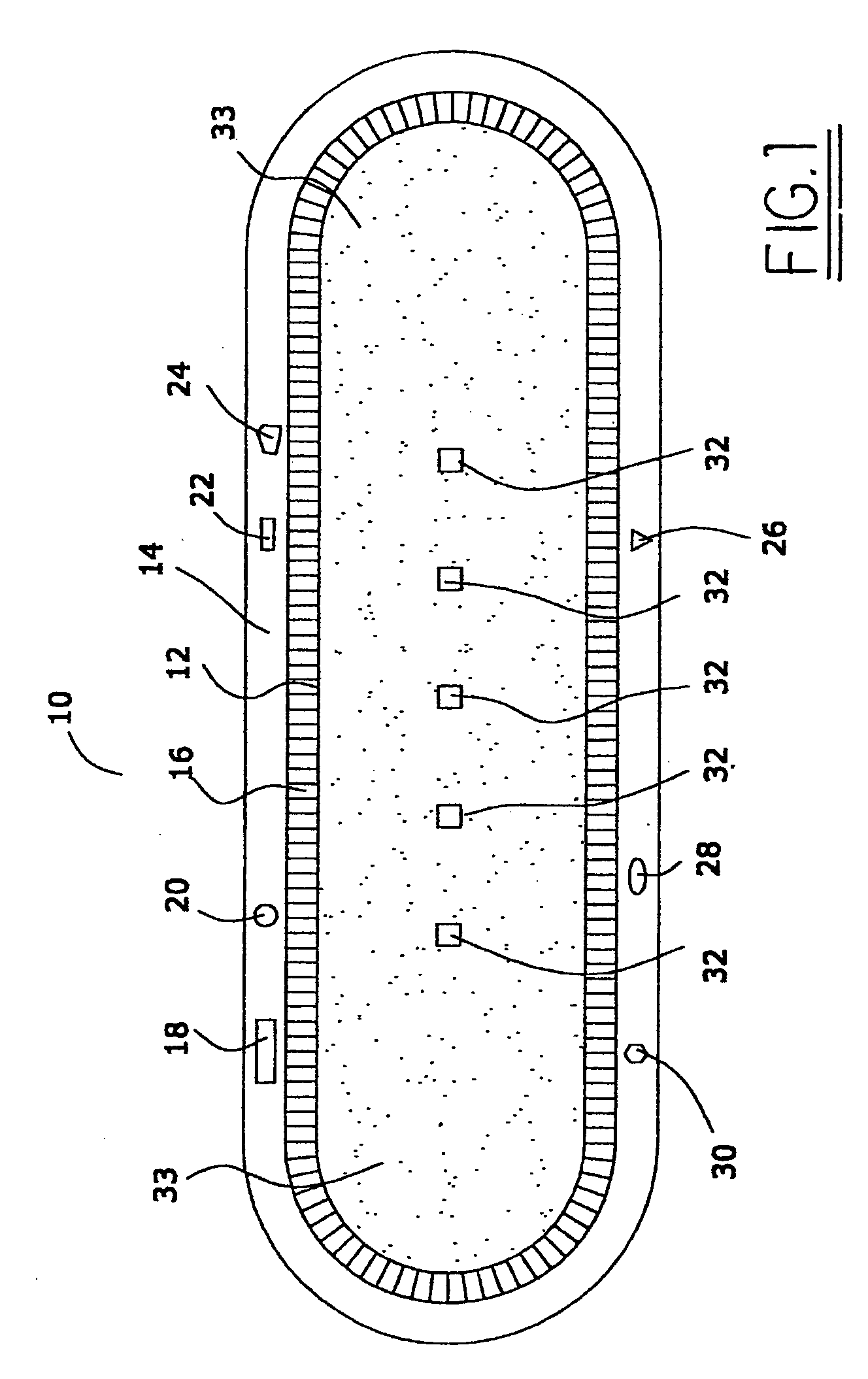
[0068]FIG. 1 is a schematic diagram of a preferred seed assembly 10 of this invention. Referring to FIG. 1, and to the preferred embodiment depicted therein, it will be seen that assembly 10 is comprised of a sealed container 12 comprised of a multiplicity of radioactive particles 33.

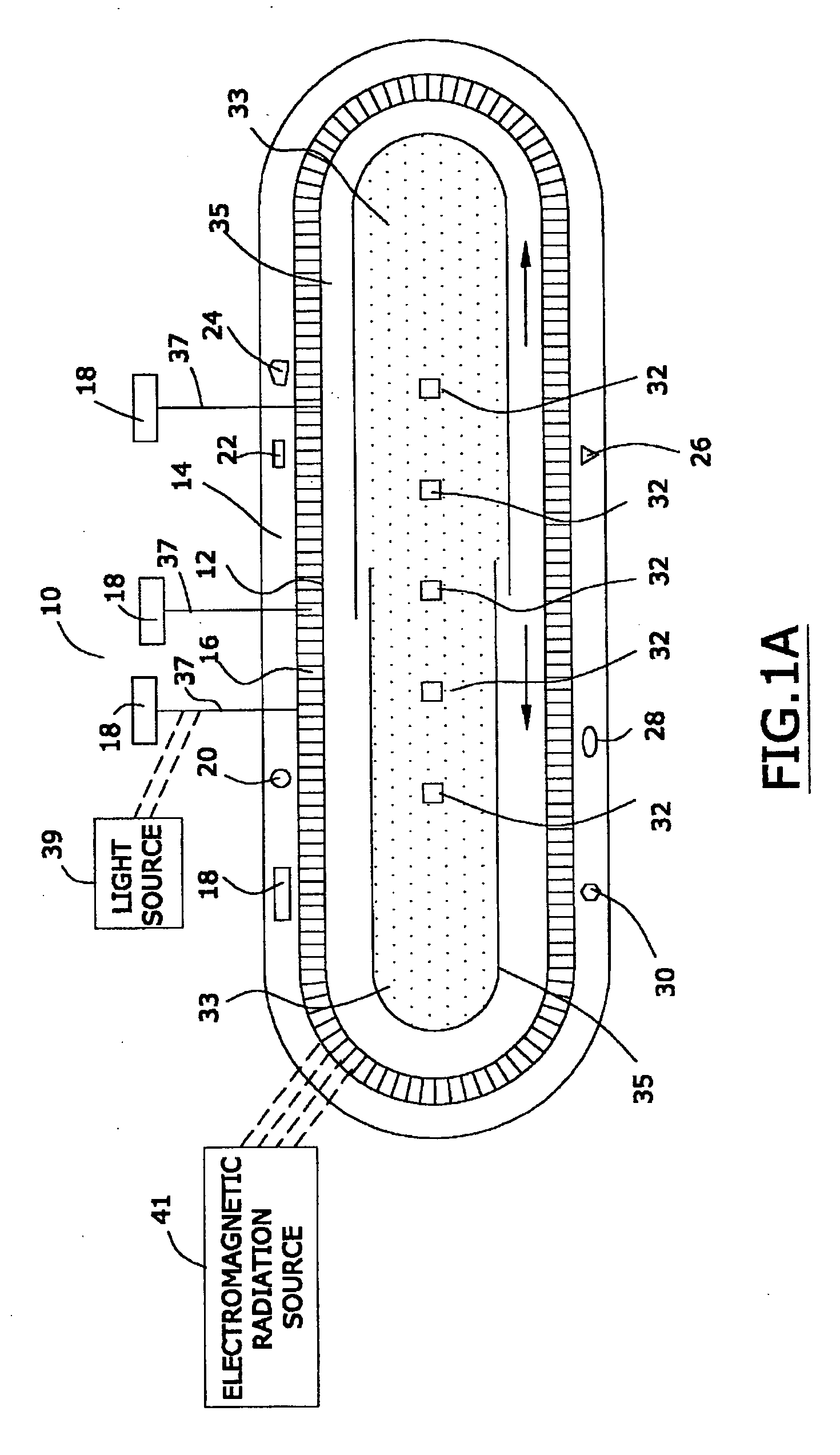
[0069] In one preferred embodiment, and referring to FIG. 1A, the assembly 10 is preferably comprised of a shield 35 that is adapted to prevent radiation from escaping from assembly 10 when such shield is in a first position, and to allow radiation to escape from assembly 10 when such shield is in a second position. It should be recognized that the depiction in FIG. 1A is merely a schematic one that does not necessarily accurately illustrate the size, scale, shape, or functioning of the shield 35.

[0070] One may use prior art radiation shields as...


PUM

PropertyMeasurementUnit
particle sizeaaaaaaaaaa
capacitanceaaaaaaaaaa
inductanceaaaaaaaaaa

Abstract

A coated assembly with an inductance of from about 0.1 to about 5 nanohenries and a capacitance of from about 0.1 to about 10 nanofarads. The coated assembly contains a stent and a coating. When the assembly is exposed to radio frequency electromagnetic radiation with a frequency of from 10 megahertz to about 200 megahertz, at least 90 percent of the electromagnetic radiation penetrates to the interior of the stent.

Description

CROSS-REFERENCE TO RELATED PATENT APPLICATION [0001] This patent application is a continuation in part of each of applicants' copending patent application Ser. No. 10 / 887,521 (filed on Jul. 7, 2004), Ser. No. 10,867,517 (filed on Jun. 14, 2004), Ser. No. 10 / 810,916 (filed on Mar. 26, 2004), Ser. No. 10 / 808,618 (filed on Mar. 24, 2004), Ser. No. 10 / 786,198, (filed on Feb. 25, 2004), Ser. No. 10 / 780,045 (filed on Feb. 17, 2004), Ser. No. 10 / 747,472 (filed on Dec. 29, 2003), Ser. No. 10 / 744,543 (fled on Dec. 22, 2003), Ser. No. 10 / 442,420 (filed on May 21, 2003), and Ser. No. 10 / 409,505 (flied on Apr. 8, 2003). The entire disclosure of each of these patent applications is hereby incorporated by reference into this specification.FIELD OF THE INVENTION [0002] A coated assembly with an inductance of from about 0.1 to about 5 nanohenries and a capacitance of from about 0.1 to about 10 nanofarads. The coated assembly contains a stent and a coating. When the assembly is exposed to radio freq...

Claims


Application Information

Patent Timeline
Patent Type & Authority Applications(United States)
IPC IPC(8): A61F2/06A61L31/08A61L31/18A61N1/16A61N2/00A61N2/06H02J7/00
CPCB82Y20/00B82Y25/00H01F1/0045H01F1/26H01F1/342H01F1/37H01F1/44A61L31/082A61L31/18A61N1/3718A61N1/375A61N2/002A61N2/06B82Y15/00A61N1/37512
Inventor WANG, XINGWUGREENWALD, HOWARD J.
Owner BIOPHAN TECH
Learn More