Tool damage/abnormality detecting device

a detection device and tool technology, applied in the direction of instruments, program control, nuclear elements, etc., can solve the problems of inability to maintain the necessary machining accuracy of workpieces, continue the same machining, and the tool is subject to damage/abnormality, etc., to achieve the effect of easy and appropriate adjustment of the allowable range of the indexes and easy adjustmen

Inactive Publication Date: 2006-06-29
FANUC LTD
View PDF3 Cites 26 Cited by
  • Summary
  • Abstract
  • Description
  • Claims
  • Application Information

AI Technical Summary

Benefits of technology

[0019] With the tool damage / abnormality detecting device according to the present invention, the allowable range for the indexes can be set easily and appropriately. According to the invention, moreover, the allowable range for the indexes can be easily set on a site of machining operation.

Problems solved by technology

With the passage of additional time, moreover, breakage of the tool, as well as its abrasion, results in damage or other similar abnormality, so that necessary machining accuracy for workpieces cannot be maintained.
In such a case, it is naturally inappropriate to continue the same machining, and the tool must be replaced with a new one.
If the result of the comparison is deviated from an allowable range of preset indexes, it is concluded that the tool is subject to damage / abnormality.
If the preset threshold values are inappropriate, detection of damage / abnormality may be delayed to cause machining failure (because the allowable range is upwardly or downwardly too wide).
If the detection of damage / abnormality is premature (or if the allowable range is upwardly or downwardly too narrow), on the other hand, tools with sufficient life expectancy may be wasted.
Actually, so far, no satisfactory technology development has been made to provide a method for appropriately setting threshold values for indexes indicative of loads that act on tools.
However, there is no designation of a specific method for setting the given coefficient.

Method used


Image

  • Tool damage/abnormality detecting device
  • Tool damage/abnormality detecting device
  • Tool damage/abnormality detecting device

Examples


Embodiment Construction

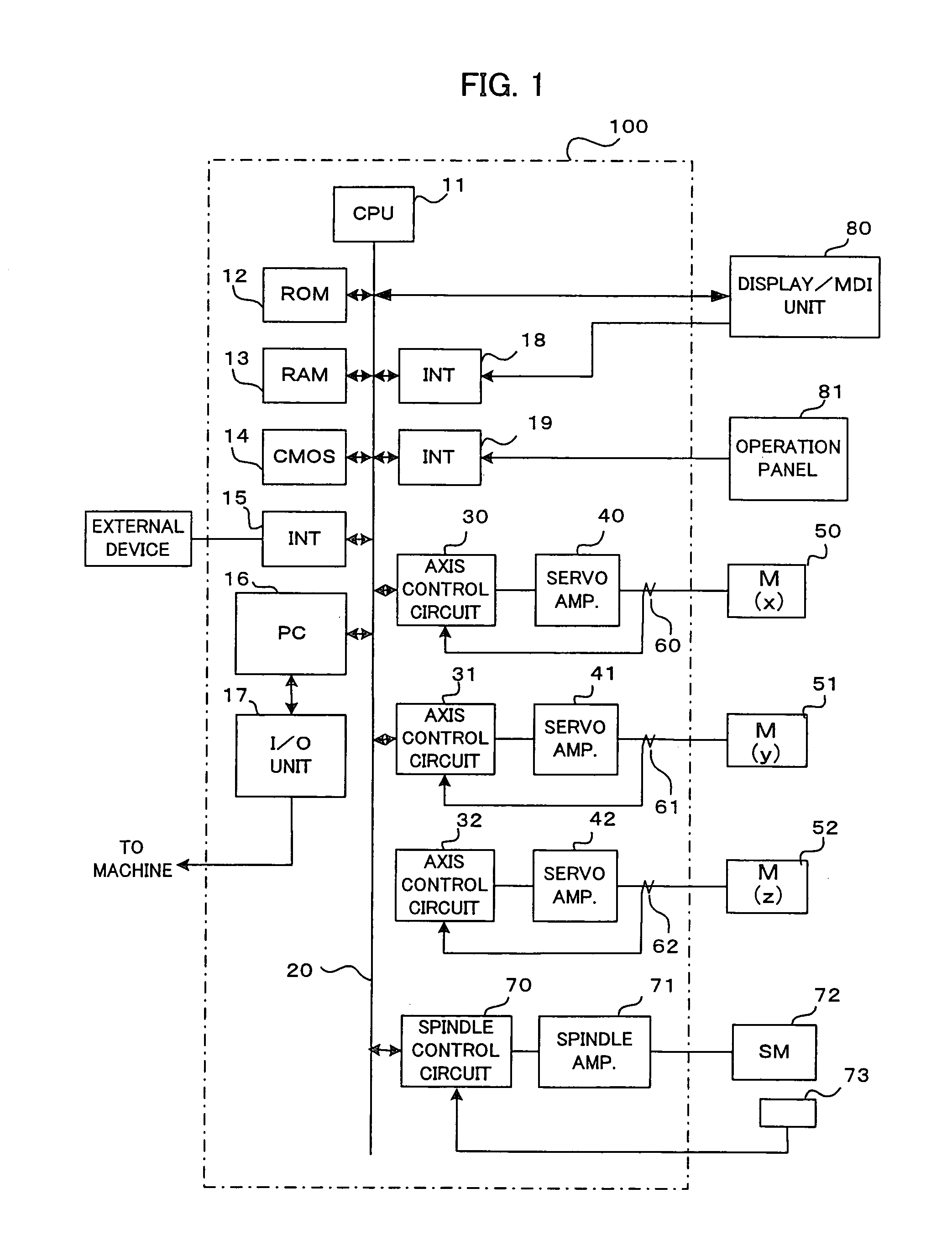
[0024]FIG. 1 is a block diagram of a control device (numerical control device) 100 for machine tool control, which doubles as a tool damage / abnormality detecting device according to the present invention. In FIG. 1, a CPU 11 is a processor for generally controlling the control device 100. The CPU 11 reads a system program from a ROM 12 through a bus 20 and controls the entire control device 100 in accordance with the system program. A RAM 13 is stored with temporary calculation data, display data, and various data that are inputted by an operator through a display / MDI unit 80. A CMOS memory 14 is formed as a nonvolatile memory that is backed up by a battery (not shown) so that it can maintain a storage state even after the control device 100 is switched off.

[0025] The CMOS memory 14 is stored with a machining program read through an interface 15, a machining program inputted through the display / MDI unit 80, etc.

[0026] Further, the ROM 12 is preloaded with various system programs f...


PUM


Abstract

A tool damage/abnormality detecting device capable of easily appropriately setting an allowable range for a value of comparison between a present value and a near past average for indexes indicative of loads on a tool. A machining cycle counter index i is adjusted to i=0, machining is performed as the loads are detected in a given period, and indexes H(i) (area S of load values, absolute value (G) of a maximum inclination between two points obtained during a decrease of loads, etc.) are acquired for n number of cycles. Thereafter, the indexes and values of comparison between the index value for a present cycle and the indexes for the n number of cycles are acquired. A first comparison value can be used for initial value setting for threshold values. If any of the comparison values is deviated from the allowable range, the threshold values are updated so that the allowable range extends, and an update history is saved. If damage/abnormality is observed visually or in any other manner, a threshold value update discontinue command is inputted, machining is stopped after completion of the cycle concerned, and update values for the latest threshold value are collected to be used as set threshold values.

Description

BACKGROUND OF THE INVENTION [0001] 1. Field of the Invention [0002] The present invention relates to a tool damage / abnormality detecting device for detecting damage / abnormality, such as breakage of a tool used in machining, in machining workpieces of the same material into one and the same shape or continuously machining a large number of workpieces, such as components of the same specifications, by using a machine tool, and more specifically, to a technique to enable the detecting device to appropriately easily set an allowable range for indexes used for tool damage / abnormality detection. Typical tools to be subjected to damage / abnormality detection include a drill of a machining center, a tapping tool for tapping work, etc. [0003] 2. Description of the Related Art [0004] In general, a tool used in a machine tool has its edge worn so that its cutting resistance gradually increases with the passage of machining time. With the passage of additional time, moreover, breakage of the too...

Claims


Application Information

Patent Timeline
Patent Type & Authority Applications(United States)
IPC IPC(8): G06F19/00
CPCB23Q17/09G05B19/4065G05B2219/37245G05B2219/37252G05B2219/41376G05B2219/50276B23Q17/0957B23Q17/0966
Inventor YASUGI, KUNIHARUMAEKAWA, SUSUMU
Owner FANUC LTD
Why Eureka
Try Eureka