Composite MEMS pressure sensor configuration

a pressure sensor and composite technology, applied in the direction of fluid pressure measurement by mechanical elements, fluid pressure measurement using elastically deformable gauges, instruments, etc., can solve the problems of reducing the yield rate, compromising the performance of the mems pressure sensor, and being larger and more expensive. , to achieve the effect of reducing the mass of the sensor, limiting the deflection, and reducing the gravity error

Active Publication Date: 2006-07-06
BROSH AMNON
View PDF7 Cites 68 Cited by
  • Summary
  • Abstract
  • Description
  • Claims
  • Application Information

AI Technical Summary

Benefits of technology

[0012] Another advantage of the present invention is that the beams in both embodiments act as a support for the diaphragm and limit its deflection. In the single layer embodiment, the thicker beams located on the centerline support the thinner diaphragm and reinforce it. In the second embodiment, the beams on the second layer provide a center support for the diaphragm of the first layer. In both cases, the combined structure becomes more stable and more resistant to ballooning, buckling, mid-plane stretching, etc.
[0013] In addition, the diaphragm-beam configuration permits the incorporation of stress isolation slots without creating a pressure leak path. The slots provide protection against in-plane stresses induced by the thermal mismatch intrinsic to die mounting.
[0019] 5. For very low range pressure sensors, sensor mass must be minimized in order to reduce gravity error. Unlike the prior art low pressure sensors, which rely on a large boss for stress magnification, the diaphragm-beam sensors employ either no boss, a small linking boss or a small protrusion.

Problems solved by technology

Thin diaphragms exhibit a number of problems: Ballooning; Mid-plane stretching under applied load; Buckling; Sensitivity to in plane stresses by thermal expansion; Bi-metallic thermal effects; Relatively large boss required to implement the required stress concentration.
This causes performance problems: High thermal zero shift; Anomalous thermal span shifts (lower or higher); Nonlinearity; Zero instability; Gravity / acceleration sensitivity.
All low pressure silicon piezoresistive sensors currently offer compromised performance: Limited to higher than desirable range; Down-rated; Have higher nonlinearity, zero drift and long term drift as compared to higher ranges specifications; Suffer from lower yields; Are Larger and more expensive; Suffer from excessive “g” sensitivity due to the large mass of the boss.
These innovations improved low pressure range performance, but fall short of needed specifications.
The crux of the problem is that current technology, which employs diaphragms to act as both the force collector and the sensing flexure, is too rigidly constrained to perform both tasks optimally.

Method used


Image

  • Composite MEMS pressure sensor configuration
  • Composite MEMS pressure sensor configuration
  • Composite MEMS pressure sensor configuration

Examples


Embodiment Construction

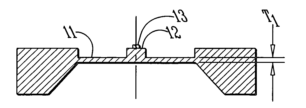
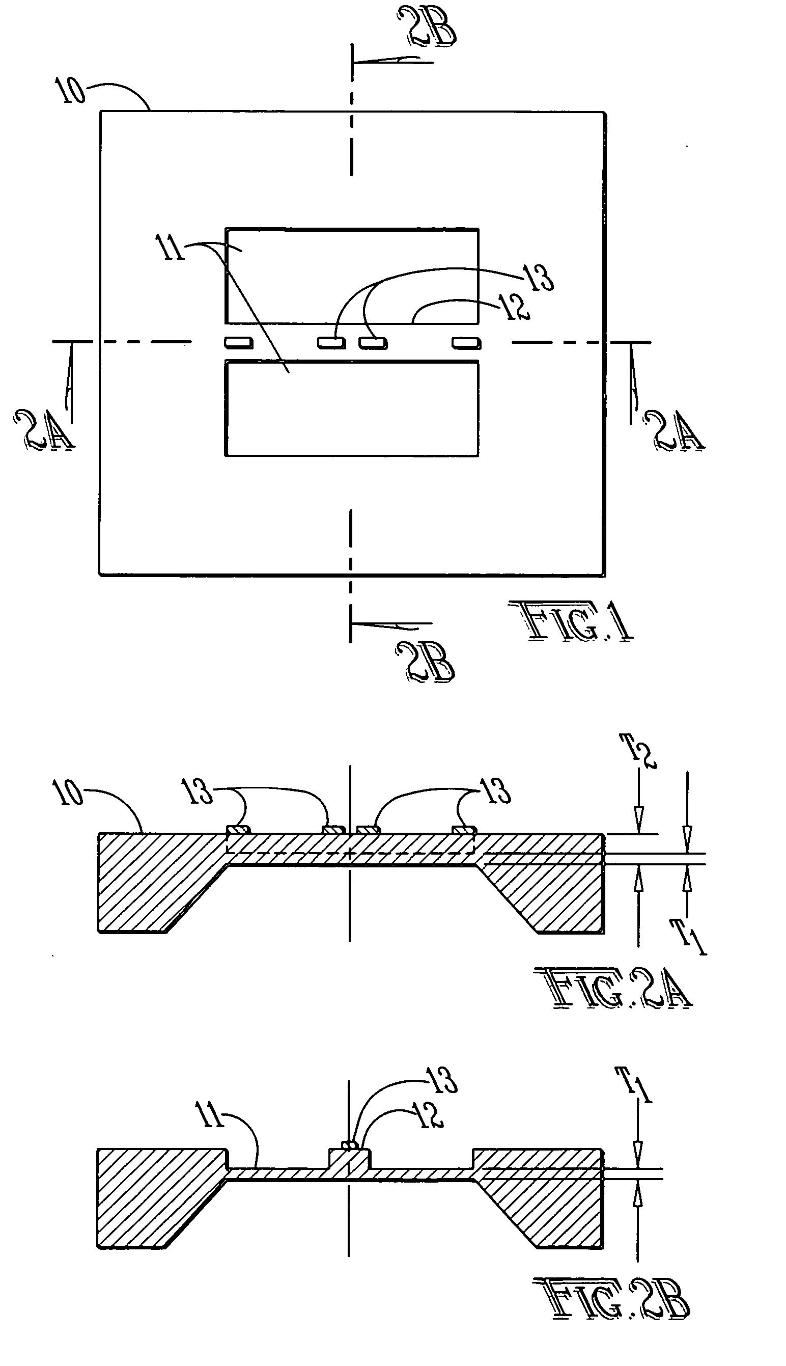
[0035] Referring to FIG. 1 the top view of pressure sensing die 10 is shown that measures pressure. Two cross-sectional views of die 10 are shown in FIG. 2A and FIG. 2B. In the shown embodiment, the bottom side of die 10 is etched to a predetermined depth in order to form a flat diaphragm of thickness T2. The top surface of the die 10 is further etched selectively around the beam to form a thinned area web / membrane 11 with thickness T1 while keeping the beam 12 at the original thickness T2. The end result is an integrated structure consisting of a constant width narrow thicker beam 12 formed along the centerline of the thinner diaphragm 11. Piezoresistive strain gages 13 are diffused, implanted, or affixed to, the narrow thicker beam. Two strain gages are place on or around the outer edge and two strain gages are placed around the center of the beam. When pressure is applied, the thin diaphragm 11 deflects. Its deflection is constrained by the thicker beam 12. This creates a force t...


PUM

PropertyMeasurementUnit
pressureaaaaaaaaaa
absolute pressureaaaaaaaaaa
absolute pressuresaaaaaaaaaa

Abstract

A pressure sensor assembly comprised of a single and dual layer diaphragm with integrated force sensing flexure, such as a cantilever beam. Strain gages are positioned on the force sensing beam. The pressure forces the diaphragm to deflect. The deflection is constrained by the beam, which is compelled to bend. The bending induces strains in strain gages located on the beam. The strain gages are connected in a Wheatstone bridge configuration. When a voltage is applied to the bridge, the strain gages provide an electrical output signal proportional to the pressure. Composite diaphragm—beam pressure sensors convert pressure more efficiently and improve sensor performance.

Description

[0001] This application claims priority from U.S. provisional patent application No. 60 / 639,340 entitled “Integral Pressure Sensing Die Configuration,” filed oh Dec. 28, 2004. That application is incorporated fully by reference herein.FIELD OF THE INVENTION [0002] The present invention relates to piezoresistive pressure sensors that are used to measure pressure by converting pressure into strain, which is sensed by strain gages. BACKGROUND OF THE INVENTION [0003] Prior art piezoresistive pressure dies are based on plain or bossed diaphragms. Strain gages are placed on the diaphragms to sense the strains created by the pressure. The strains depend on diaphragm geometry. In order to produce adequate strains in low pressure range sensors, thin diaphragms must be used. Thin diaphragms exhibit a number of problems: Ballooning; Mid-plane stretching under applied load; Buckling; Sensitivity to in plane stresses by thermal expansion; Bi-metallic thermal effects; Relatively large boss requir...

Claims


Application Information

Patent Timeline
Patent Type & Authority Applications(United States)
IPC IPC(8): G01L7/08
CPCG01L9/0052
Inventor BROSH, AMNON
Owner BROSH AMNON
Why Eureka
Try Eureka