Method and apparatus for plasma gasification of waste materials

a waste material and plasma gasification technology, applied in the direction of greenhouse gas reduction, emission prevention, combustion types, etc., can solve the problems of substantial public concerns relative to land space allocation and environmental damage, the daily generation of solid waste materials such as municipal solid waste and its disposal are major problems, and the use of landfill sites for the disposal of such solid waste cannot solve the problems. , to achieve the effect of simple and inexpensive design, construction and operation

Inactive Publication Date: 2006-07-06
PLASMA WASTE RECYCLING
View PDF4 Cites 27 Cited by
  • Summary
  • Abstract
  • Description
  • Claims
  • Application Information

AI Technical Summary

Benefits of technology

[0012] Accordingly, it is a general object of the present invention to provide an improved method and apparatus for plasma gasificat

Problems solved by technology

As is generally well-known, the daily generation of solid waste material, such as Municipal Solid Waster (MSW) and its disposal thereof have become major problems in the past few decades as more and more waste is being generated by residential and commercial facilities.
The use of landfill sites for the disposal of such MSW does not solve the problems due to all of the existing sites becoming full coupled with the fact that they contaminate groundwater and adjacent properties.
As a result, there are substantial public concerns relative to land space allocation and environmental damage.
However, these incinerator EFW systems tend to cause a great deal of air pollution.
However, plasma torch type furnaces are not economical due

Method used


Image

  • Method and apparatus for plasma gasification of waste materials
  • Method and apparatus for plasma gasification of waste materials
  • Method and apparatus for plasma gasification of waste materials

Examples


second embodiment

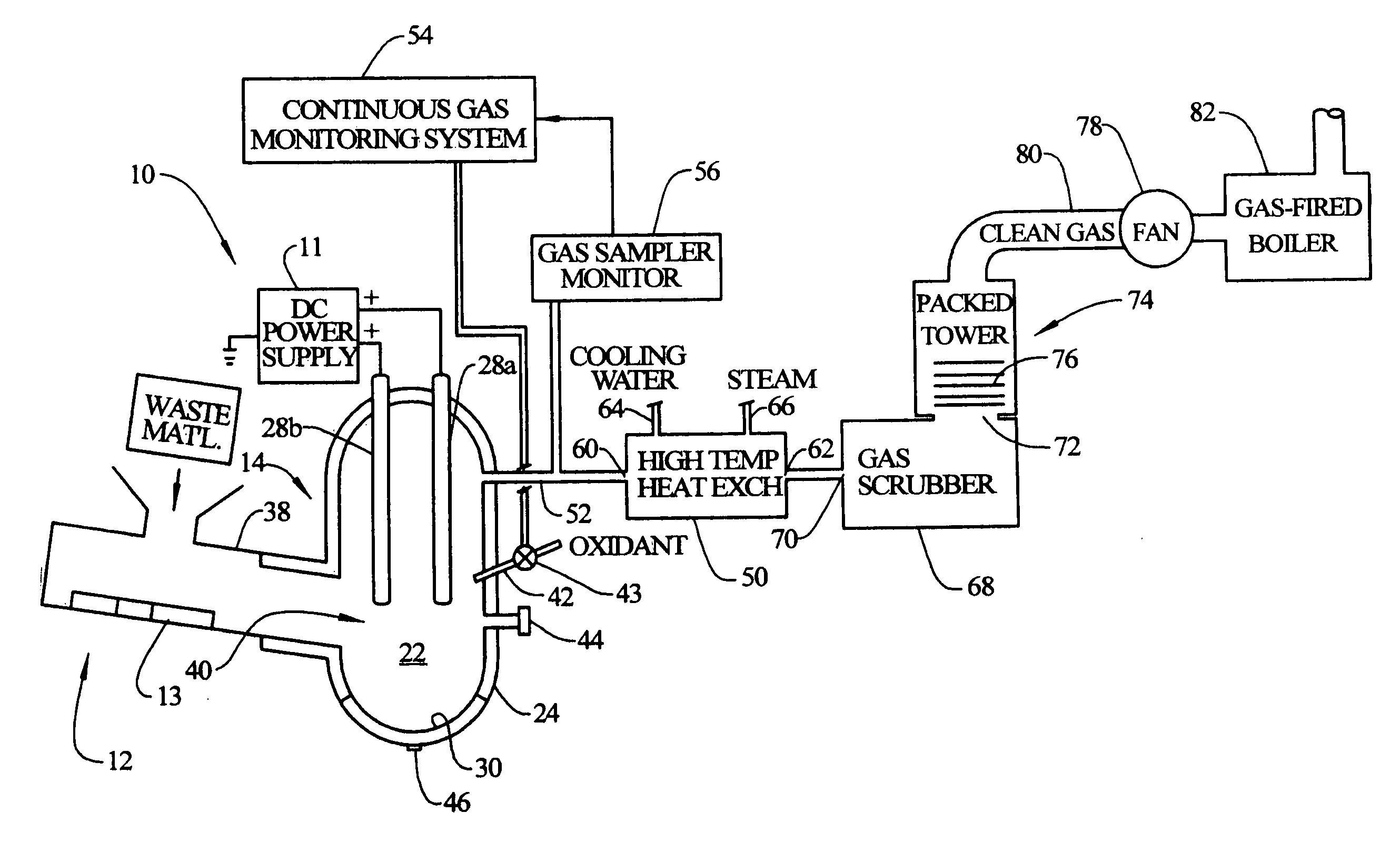
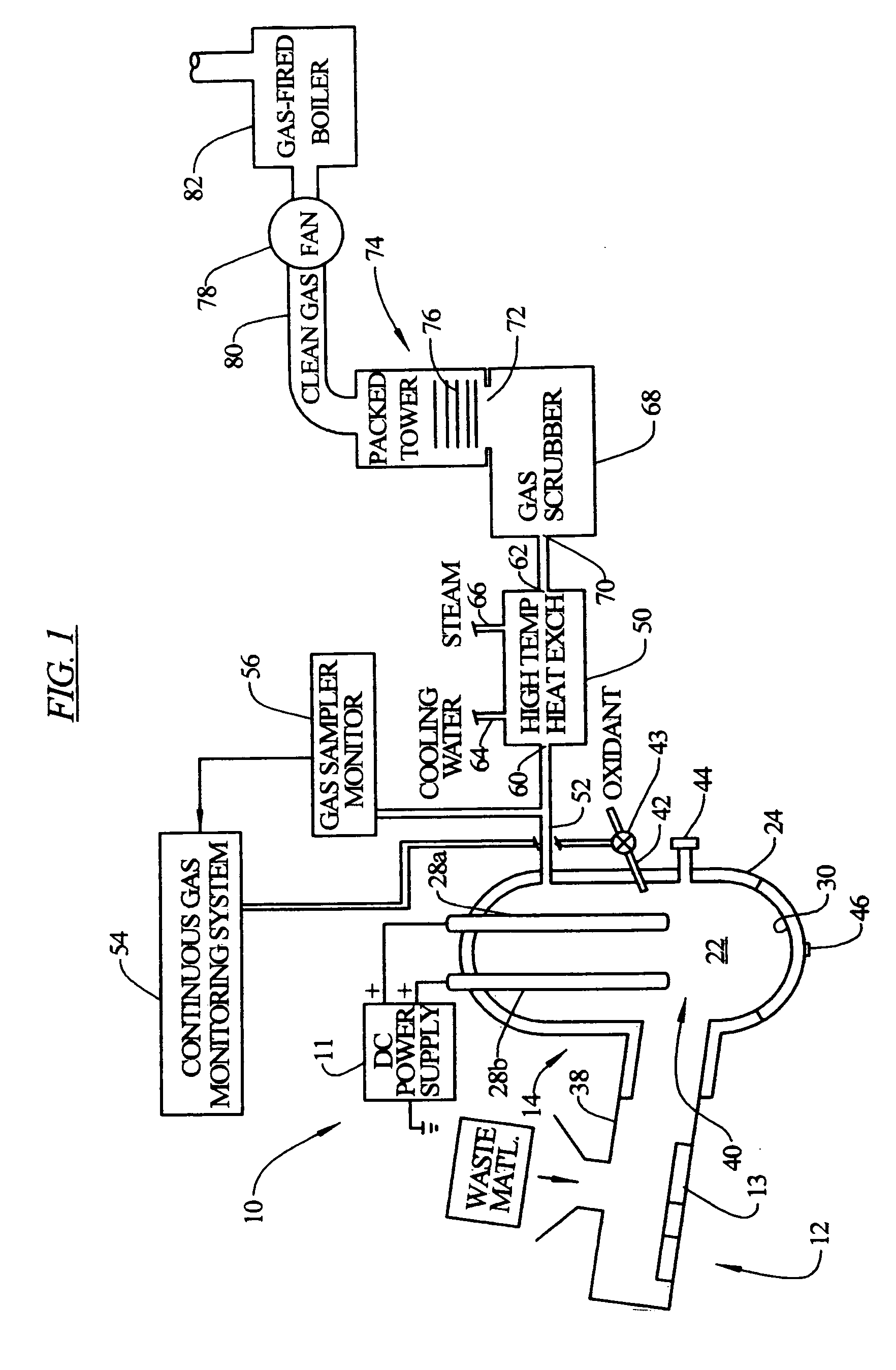
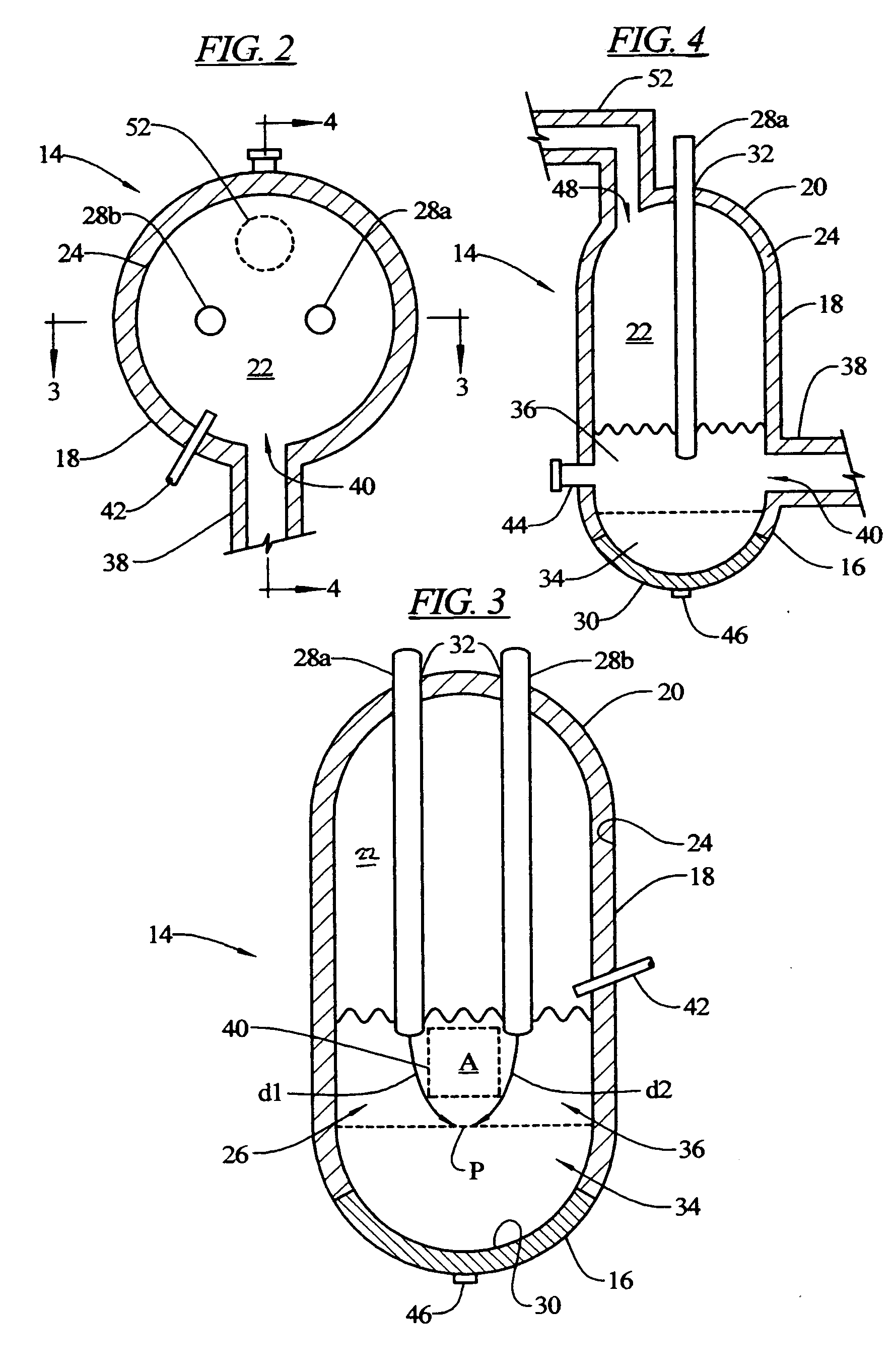
[0056] In FIG. 5, there is shown a cross-sectional view of a refractory-lined vessel 114 of the present invention for use in the apparatus of FIG. 1. FIG. 6 is a cross-sectional view of the reactor vessel 114 of FIG. 5, taken along the lines 6-6 thereof. FIG. 7 is a cross-sectional view of the reactor vessel 114 of FIG. 5, taken along the lines 7-7 thereof. The reactor vessel 114 is substantially identical to the reactor vessel 14 of FIGS. 2-4, except that there is provided two feeder mechanisms and only a single anode electrode. Except for these differences, the structure and operation of the reactor vessel 114 is identical to the reactor vessel 14.

[0057] The reactor vessel 114 has the same shape and dimensions as the reactor vessel 14 illustrated in FIGS. 2-4. In particular, The reactor vessel 114 is formed by a generally semi-spherical closed bottom 116 and a circumferential side wall 118 which extends upwardly from the closed bottom 116 and terminates in a generally semi-spheric...

third embodiment

[0060] In FIG. 8, there is shown a cross-sectional view of a refractory-lined vessel 214 of the present invention for use in the apparatus of FIG. 1. FIG. 9 is a cross-sectional view of the reactor vessel 214 of FIG. 8, taken along the lines 9-9 thereof. FIG. 10 is a cross-sectional view of the reactor vessel 214 of FIG. 8, taken along the lines 10-10 thereof. The reactor vessel 214 is substantially identical to the reactor vessel 14 of FIGS. 2-4, except that there is provided two feeder mechanisms. Except for this difference, the structure and operation of the reactor vessel 214 is identical to the reactor vessel 14.

[0061] The reactor vessel 214 has the same shape and dimensions as the reactor vessel 14 illustrated in FIGS. 2-4. In particular, The reactor vessel 214 is formed by a generally semi-spherical closed bottom 216 and a circumferential side wall 218 which extends upwardly from the closed bottom 216 and terminates in a generally semi-spherical upper end 220 so as to create ...

fourth embodiment

[0064] In FIG. 11, there is shown a cross-sectional view of a refractory-lined vessel 314 of the present invention for use in the apparatus of FIG. 1. FIG. 12 is a cross-sectional view of the reactor vessel 314 of FIG. 11, taken along the lines 12-12 thereof. FIG. 13 is a cross-sectional view of the reactor vessel 314 of FIG. 11, taken along the lines 13-13 thereof. The reactor vessel 314 is substantially identical to the reactor vessel 14 of FIGS. 2-4, except that there is provided two feeder mechanisms. Except for this difference, the structure and operation of the reactor vessel 314 is identical to the reactor vessel 14.

[0065] The reactor vessel 314 has the same shape and dimensions as the reactor vessel 14 illustrated in FIGS. 2-4. In particular, the reactor vessel 314 is formed by a generally semi-spherical closed bottom 316 and a circumferential side wall 318 which extends upwardly from the closed bottom 316 and terminates in a generally semi-spherical upper end 320 so as to c...


PUM


Abstract

A method and apparatus for plasma gasification of waste materials consisting of organic and inorganic portions is provided which includes a refractory-lined reactor vessel, a feeder mechanism, and a DC electrode device. The refractory-lined reactor vessel has a processing chamber formed therein. The feeder mechanism feeds continuously waste materials into the processing chamber at a controlled feed rate. The DC electrode device is used for heating the processing chamber to a sufficient temperature so as to convert the organic portions of the waste materials to a synthetic gas consisting of hydrogen and carbon monoxide and to a carbon particulate, and to convert the inorganic portions of the waste materials to a molten material consisting of a lower metallic layer and a slag layer formed on top of the metallic layer.

Description

BACKGROUND OF THE INVENTION [0001] 1. Field of the Invention [0002] This invention relates generally to methods and apparatuses for the treatment of waste materials and more particularly, the present invention relates to an improved method and apparatus for plasma gasification of hazardous and non-hazardous waste materials by utilizing at least one graphite DC electrode in a refractory-lined reactor vessel. [0003] 2. Description of the Prior Art [0004] As is generally well-known, the daily generation of solid waste material, such as Municipal Solid Waster (MSW) and its disposal thereof have become major problems in the past few decades as more and more waste is being generated by residential and commercial facilities. The use of landfill sites for the disposal of such MSW does not solve the problems due to all of the existing sites becoming full coupled with the fact that they contaminate groundwater and adjacent properties. As a result, there are substantial public concerns relativ...

Claims


Application Information

Patent Timeline
IPC IPC(8): F23G5/10F23B90/00
CPCF23G5/0276F23G5/085F23G5/46F23G5/50F23G2201/40F23G2207/108F23G2207/30F23J15/022F23J15/04F23J15/06F23J2215/30Y02E20/363Y02E20/30
Inventor VERA, RODRIGO B.
Owner PLASMA WASTE RECYCLING
Why Eureka
Try Eureka