Remotely controlled model airplane having deflectable centrally biased control surface

a centrally biased control and remote control technology, applied in the direction of remote control toys, magnetic bodies, automatic actuation, etc., can solve the problems of primarily limited control of engine speed and operation, escapements lacking sufficient power to deflect elevators, etc., and achieve selective deflecting one or more control surfaces. low cost

Inactive Publication Date: 2006-07-06
CLANCY ANDY J
View PDF31 Cites 24 Cited by
  • Summary
  • Abstract
  • Description
  • Claims
  • Application Information

AI Technical Summary

Benefits of technology

[0015] A still further object of the present invention is to provide a low cost operating system for selectively deflecting one or more control surfaces of a model airplane.

Problems solved by technology

Generally, such escapements lacked sufficient power to deflect the elevator to obtain a change in pitch or to deflect the ailerons to obtain a left or right rolling moment about the longitudinal axis.
Moreover, control of the engine speed and operation was primarily limited to shutting down the engine, which engine was usually a single cylinder internal combustion engine.

Method used


Image

  • Remotely controlled model airplane having deflectable centrally biased control surface
  • Remotely controlled model airplane having deflectable centrally biased control surface
  • Remotely controlled model airplane having deflectable centrally biased control surface

Examples


Embodiment Construction

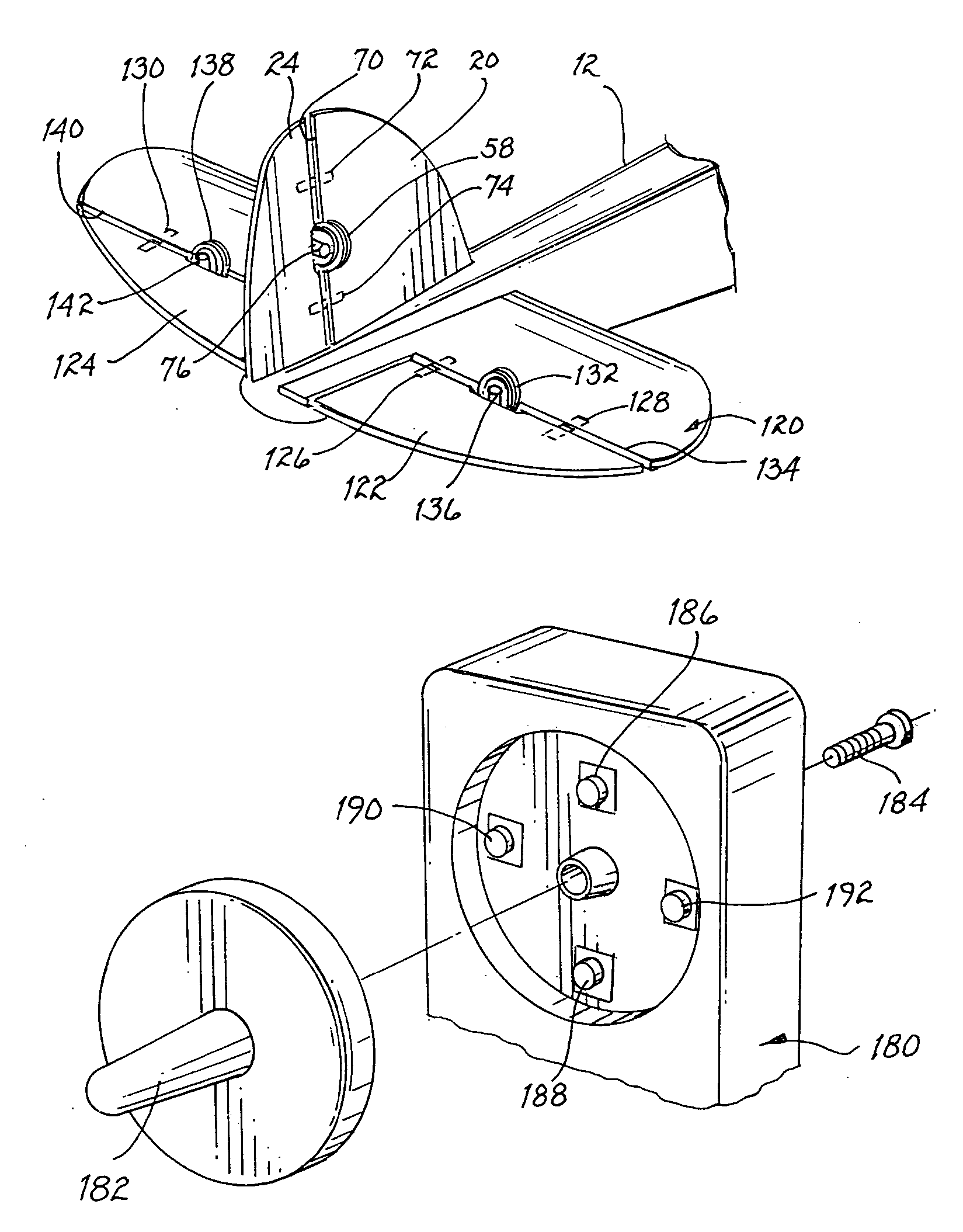
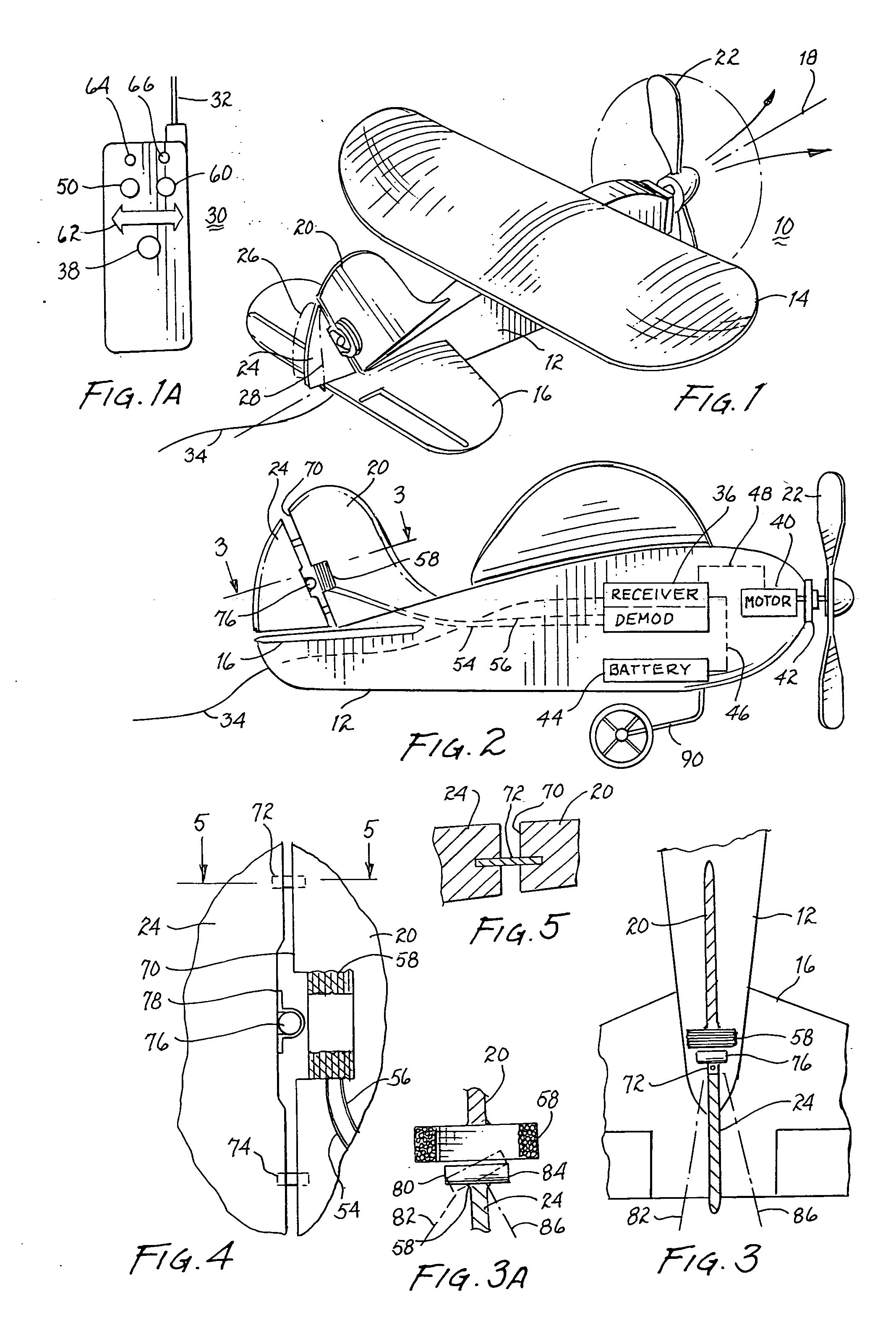
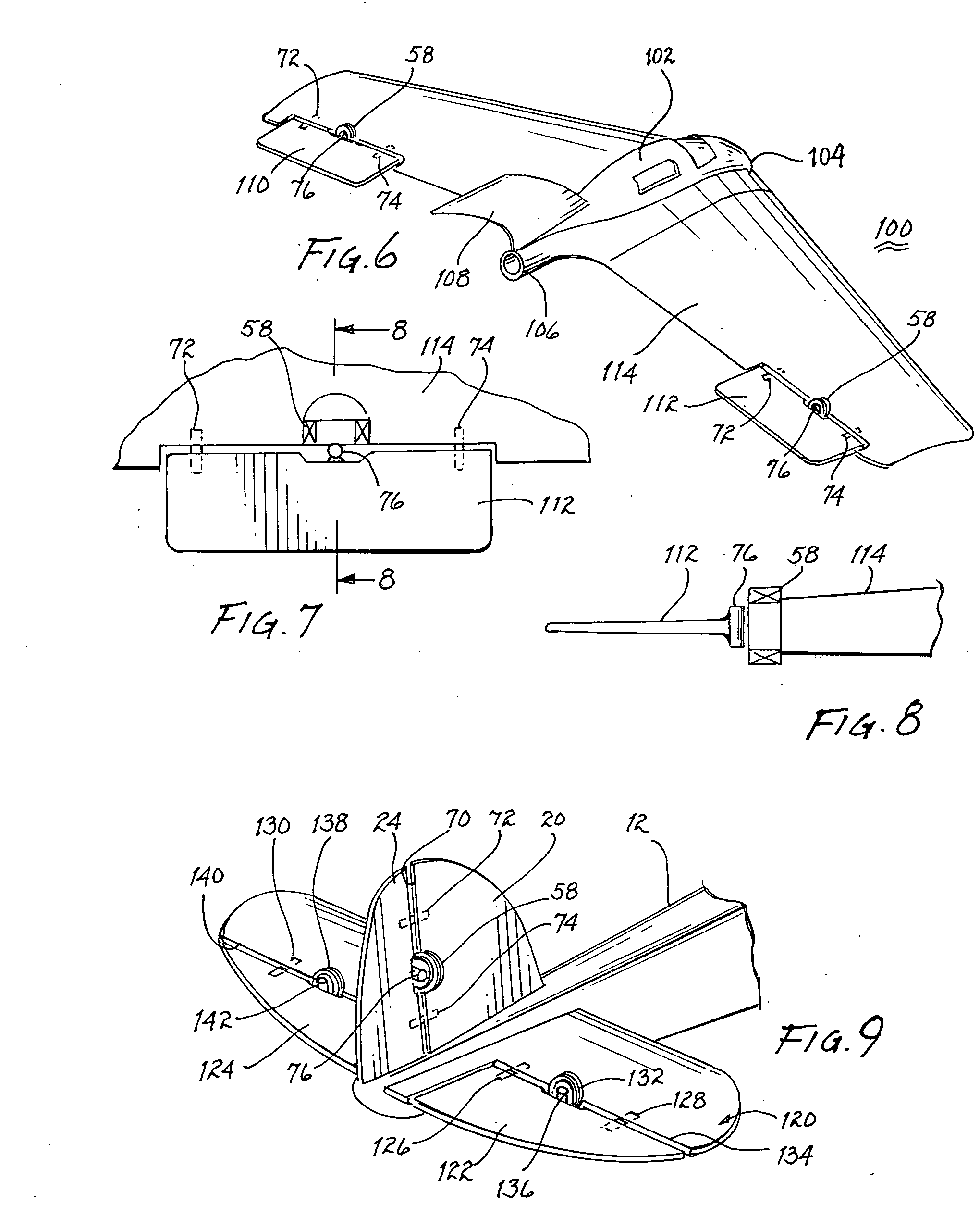
[0036] Referring to FIG. 1, there is shown a model airplane 10. The airplane includes a fuselage 12 supporting a wing 14 for generating lift upon forward motion of the plane. A horizontal stabilizer 16 provides stability in the pitch axis and is generally in alignment with longitudinal axis 18. However, for stability purposes, the horizontal stabilizer may have a small negative angle of attack. A vertical stabilizer 20 provides stability about the yaw axis of the model airplane. A propeller 22 is turned by a motor (see FIG. 2) mounted within fuselage 12 and provides thrust for forward motion of the model airplane. A rudder 24 is hingedly attached to vertical stabilizer 20 and upon movement left or right, as depicted by dashed lines 26, 28, the direction of flight of the airplane will change to the left or to the right, respectively.

[0037] Model airplane 10 is remotely controlled, sometimes referred to as radio controlled. Referring jointly to FIGS. 1, 1A and 2, the remote control a...


PUM


Abstract

A remotely controlled model airplane includes a receiver responsive to signals from a transmitter to control the direction of flight of the model airplane. The receiver, powered by a battery, demodulates the signal transmitted by the transmitter to selectively energize an electrical coil to generate a magnetic field of a first or second polarity. A rudder pivotally attached to the vertical stabilizer includes a magnet responsive to the magnetic fields generated and is urged in one direction or the other resulting in commensurate pivotal movement of the rudder. A hinge interconnecting the rudder and vertical stabilizer urges return to center of the rudder after it has been deflected left or right by the magnet responding to the magnetic field created as a result of a signal transmitted by the transmitter. An electric motor also under control of the transmitter and receiver may be incorporated to rotate a propeller to provide thrust and forward motion of the model airplane. By employing a transmitter to selectively transmit a plurality of signals, control surfaces of the model airplane can be deflected to provide 2-axis control to selectively alter the direction and pitch of the model airplane.

Description

BACKGROUND OF THE INVENTION [0001] 1. Field of the Invention [0002] The present invention relates to control systems for remotely controlled model airplanes and, more particularly, to magnetically operated centrally biased control surfaces for a model airplane. [0003] 2. Description of Related Prior Art [0004] Remotely controlled, and formerly referred to as radio controlled, model airplanes have been built and flown as a hobby since the 1940s when vacuum tube operated transmitters and receivers became available for use in model airplanes. With advances in the transmitter / receiver art, there have been significant size and weight reductions in the related equipment and there have been significant improvements in reducing the electrical power requirements. With such reductions in size and weight, smaller and lighter model airplanes became possible to be remotely controlled. [0005] Initially, the control system actuated by a signal from the receiver was a rubber band driven escapement ...

Claims


Application Information

Patent Timeline
Patent Type & Authority Applications(United States)
IPC IPC(8): B64C13/00
CPCA63H27/02A63H30/04
Inventor CLANCY, ANDY J.
Owner CLANCY ANDY J
Why Eureka
Try Eureka