
Attenuation device

a technology of attenuation device and cylinder, which is applied in the direction of vibration dampers, cosmonautic components, cosmonautic parts, etc., can solve the problems of loss of attenuation (even a possible amplification), high number of separations or bridges in each horizontal layer, etc., to achieve less rigidity, increase and decrease the proportions of each material, and reduce the effect of rigidity

Inactive Publication Date: 2006-07-06
EADS CASA ESPACIO
View PDF9 Cites 2 Cited by
  • Summary
  • Abstract
  • Description
  • Claims
  • Application Information

AI Technical Summary

Benefits of technology

[0019] Another advantage of the present invention is that elastic and dampening means form part of the structure itself, such that they are integrated along its entire surface and allow being adjusted to interfaces of large dimensions such as in the field of space vehicles such as shuttles and / or satellites. Therefore, low and mid frequency vibrations (0 to 2000 Hz) of long duration, lasting several minutes, induced by engines and cyclic operation elements, and short duration transitory phenomena such as shocks induced by separations and which generate vibrations in a very wide spectrum (up to 10000 Hz) but of a duration of a thousandth of a second, are attenuated and dampened.
[0020] The advantage of this arrangement is that it allows managing the contribution of each element in the manner most suitable to the application requirements. If more dissipating function and less rigidity are required, it will suffice to increase and decrease the proportions of each material respectively. Taken to the limit, the functions of matrix and fibre could be reversed.
[0021] Consequently, the configuration described allows resolving the problem of compatibility between the minimum rigidity required for flying and the attenuation capacity. On the one hand the matrix, an elastic material, provides the mechanical properties required for the fibre, a surface of revolution, to operate suitably, as the matrix is confined in the fibre. On the other hand this contribution does not eliminate the attenuation and filtering capacities as the slotted surface of revolution is still the main load pathway since it is the most rigid.
[0022] Another advantage added by the fibre-matrix composite in relation to compatibility between flying and filtering is the non-linearity in its response to external loads. While the slotted surface of revolution operates on an elastic basis, i.e. linear, the elastic material operates on an inelastic basis, i.e. non-linear, which contributes to the isolating capacity of the system, as the external loads increase deformations of the matrix, the latter responds by increasing rigidity due to its elastic nature.
[0023] The aforementioned phenomenon is very effective even when the elastic material is sufficiently confined. This confinement is ensured by the configuration of the slotted surface of revolution.
[0024] Thus, when the slotted surface of revolution is deformed such that it decreases the thickness of the slots, the elastic material occupying the slots is forced to compress and tries to expand in a direction that is perpendicular to that of the deformation, which is partially prevented by the elastic material occupying the rest of the slot. With an angled slot arrangement, the same effect is achieved whether the deformation is in the vertical direction or in the horizontal direction.

Problems solved by technology

The disclosed adaptor device has a series of drawbacks derived from its construction.
For example, one drawback is derived from the high number of separations or bridges existing in each horizontal layer and, generally, in the slotted hollow cylinder.
This translates into a loss of attenuation (even a possible amplification) at certain frequencies associated to cylindrical structure breathing modes and support conditions with axial symmetry.
Another drawback is the loss of rigidity due to the high number of horizontal layers and also the high number of horizontal slots per layer.
In the same manner its contribution to damping is scarcely effective.
However, these deformations are at most half the movement generated between the upper and lower interfaces, demultiplying the reaction to shear force.
The most important drawback of this configuration is, in any case, the inability of decoupling the contradictory attenuation and rigidity requirements.

Method used


Image

  • Attenuation device
  • Attenuation device
  • Attenuation device

Examples


Embodiment Construction

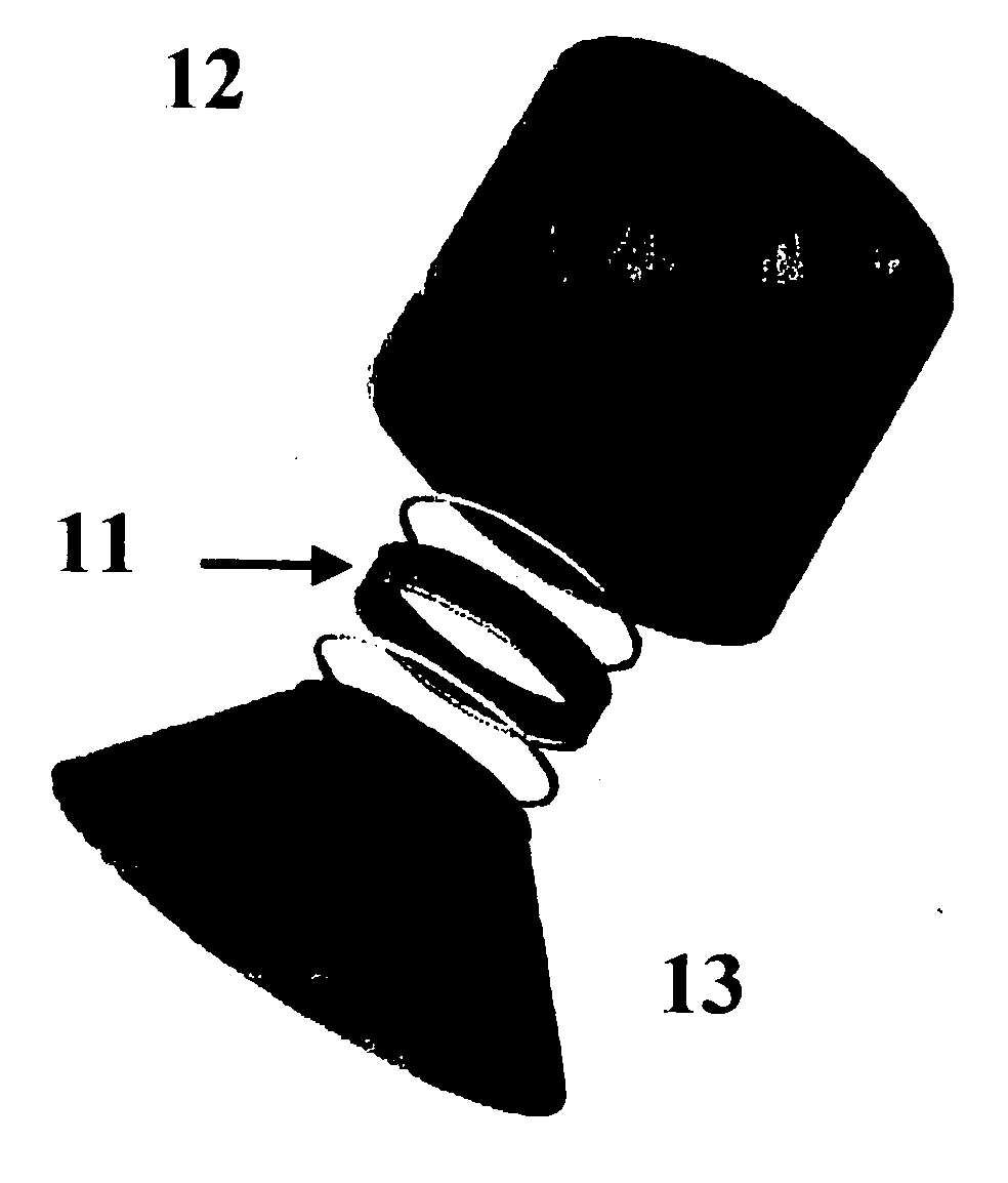
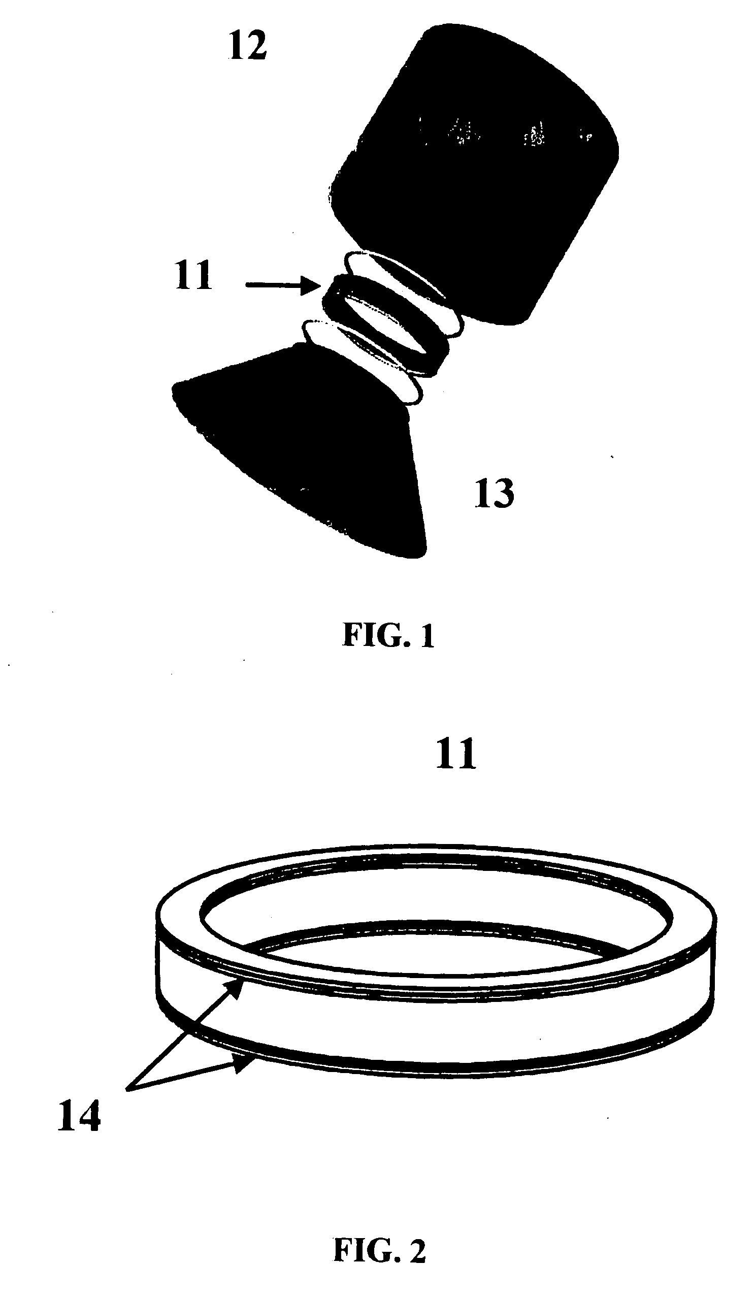
[0039]FIG. 1 shows an attenuating device 11 connected simultaneously to an upper interface 12 and a lower interface 13 corresponding to the structure of a space vehicle capable of flying in space outside the Earth's atmosphere.

[0040] In said figure it can be observed that the primary structures in charge of the structural continuity and integrity of the vehicle consist in large cylindrical or conical structures, generally with revolution symmetry, which propagate through themselves the vibratory phenomena produced during flight, without hardly dampening them due to their low dissipation coefficient and occasionally amplifying them at certain frequencies. Accordingly, the equipment and payloads must be qualified to endure this environment, which leads to greater complexity in their structural design.

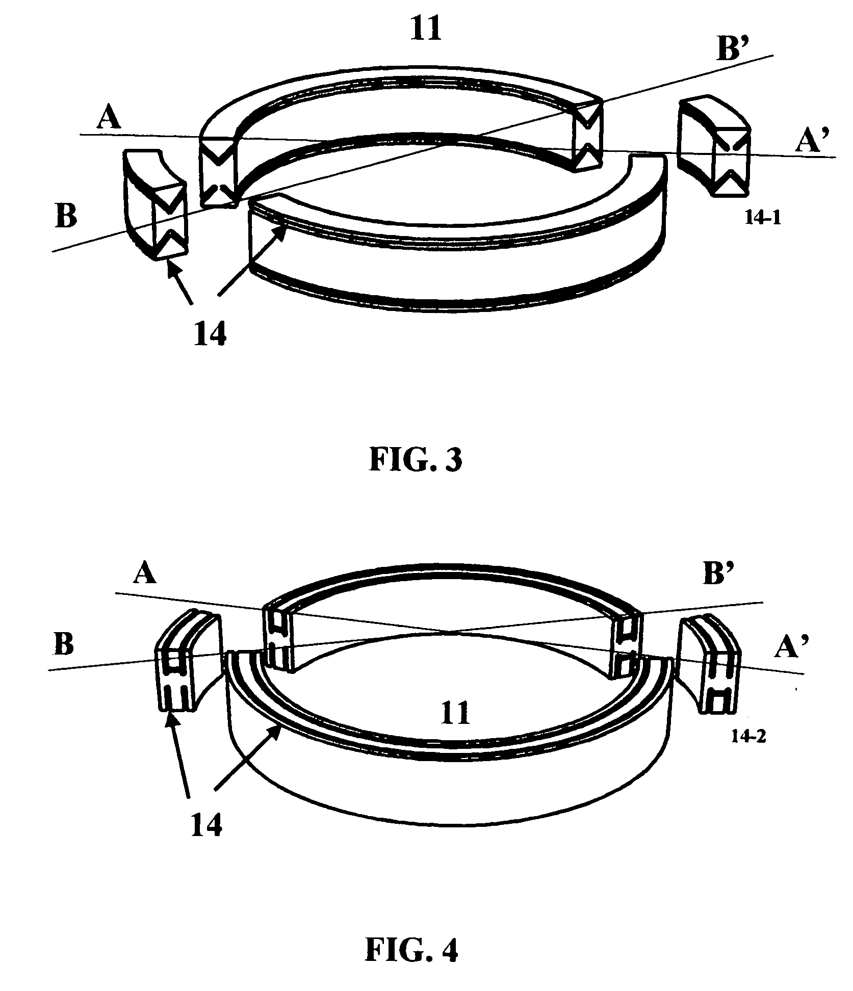
[0041]FIG. 2 shows in turn the attenuating device comprising a surface of revolution of cylindrical cross section, for example, a straight hollow cylinder 11 between the vertical sides ...


PUM

PropertyMeasurementUnit
Elasticityaaaaaaaaaa
Attenuation coefficientaaaaaaaaaa
Viscoelasticityaaaaaaaaaa

Abstract

The attenuation device of the present invention comprises a surface of revolution (11) of circular cross section, such that a set of slots (14) is distributed between the sides of the surface of revolution (11) and adapted to confine an elastic material (15) within the limits defined by the slots (14), generating a structural labyrinth for load passage from a lower interface of the surface of revolution (11) to an upper interface.

Description

OBJECT OF THE INVENTION [0001] The present invention generally refers to an attenuating device for vibrations and shockwaves which are transmitted through a chain of structures belonging to a vehicle. [0002] More specifically, the present invention refers to a passive type of attenuating device which reduces vibrations and shockwaves generated during flight in a space vehicle and transmitted through the structure of the space vehicle. STATE OF THE ART [0003] Passive attenuation devices are known in the state of the art, U.S. Pat. No. 6,202,961 by Wilke et al., for example, discloses a passive attenuation device reducing vibrations and shockwaves generated during the spacecraft flight. [0004] This passive attenuation device comprises a straight circular hollow cylinder in which a set of horizontal rectangular slots have been made, distributed in several vertical planes or layers. [0005] The horizontal slots are distributed so that they draw spatial curves in the manner of helices, i....

Claims


Application Information

Patent Timeline
IPC IPC(8): B64G1/00B64G1/64F16F1/32F16F1/366F16F1/371F16F1/373F16F1/393F16F3/12F16F7/00F16F9/30F16F15/08
CPCB64G1/641B64G2001/228F16F1/32F16F1/366F16F1/371F16F1/3732F16F1/393F16F3/12F16F7/00F16F9/30F16F15/08F16F15/085B64G1/228B64G1/6425
Inventor LANCHO DONCEL, MIGUEL
Owner EADS CASA ESPACIO
Learn More