Antenna for detection of partial discharges in a chamber of an electrical instrument

an electrical instrument and partial discharge technology, applied in the direction of instruments, air-break switches, testing vessel construction, etc., can solve the problems of poor uhf frequency, interference with measurements, and inability to properly use any antenna signal, so as to improve the sensitivity of the antenna, accurate partial discharge measurements, and the effect of improving the sensitivity

Inactive Publication Date: 2006-07-06
ALSTOM TECH LTD
View PDF11 Cites 33 Cited by
  • Summary
  • Abstract
  • Description
  • Claims
  • Application Information

AI Technical Summary

Benefits of technology

[0010] An object of the invention is to remedy those drawbacks by providing a sensor of relatively small dimensions and which presents a transfer function that is satisfactory in the ultrahigh frequency range, thus making it possible to perform accurate measurements of partial discharges by placing the sensor in any available opening in the tank of the electrical equipment, for example in an emptying valve in the tank of an oil-insulated transformer.
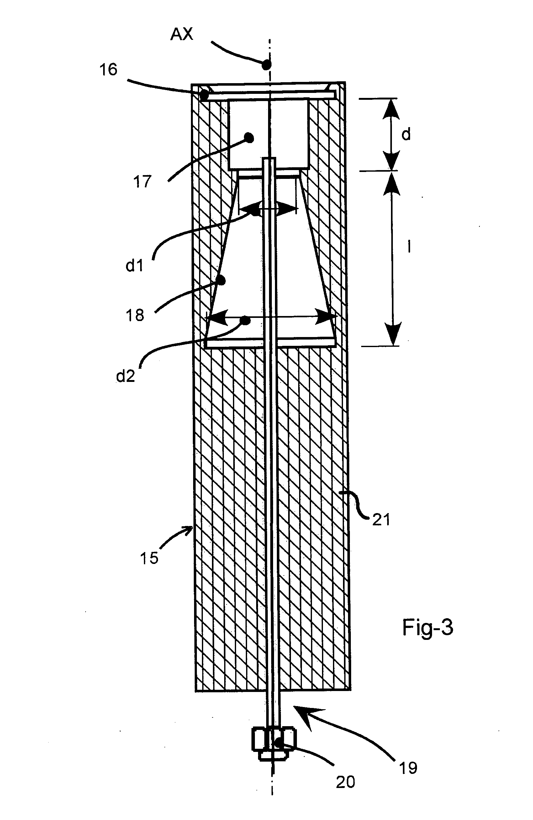
[0011] For this purpose, the invention provides a sensor for detecting partial discharges in an electrical equipment tank filled with a dielectric fluid, the sensor comprising an antenna sensitive to the electromagnetic waves generated by such partial discharges, wherein said antenna is formed by two electrodes separated by a dielectric resonator. This makes it possible to make accurate measurements of partial discharges using a sensor that is adapted to be inserted, in particular into an emptying valve.
[0012] In a preferred embodiment, the first electrode is in the form of a disk, the second electrode is in the form of a truncated cone having plane end...

Problems solved by technology

For several years, measurements have commonly been performed in the HF and very high frequency (VHF) frequency ranges to detect the impulses of partial electric discharges in electrical equipment installed in a casing filled with a dielectric fluid (a liquid or a gas), but that technique presents drawbacks.
Corona discharges taking place in the vicinity of the equipment generate high intensity electromagnetic waves in the same HF and VHF frequency ranges up to about 200 megahertz (MHz) and that significantly interferes with the measurements.
No provision is made in that device to be able to remove the antenna from its housing without temporarily taking the equipment out of service, since removing the antenna requires sealing between the gas inside the casing and the outside air to be broken...

Method used


Image

  • Antenna for detection of partial discharges in a chamber of an electrical instrument
  • Antenna for detection of partial discharges in a chamber of an electrical instrument
  • Antenna for detection of partial discharges in a chamber of an electrical instrument

Examples


Embodiment Construction

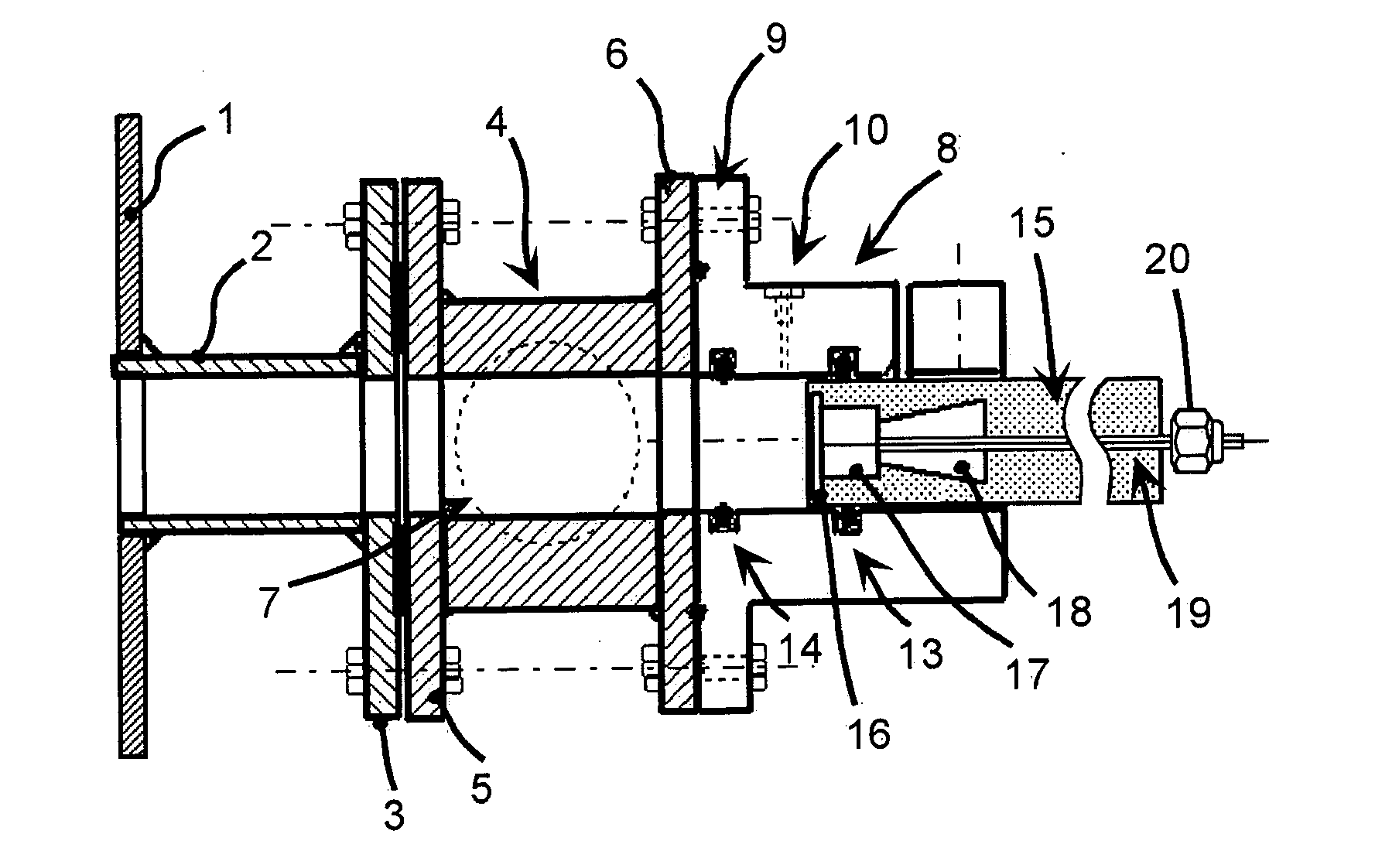
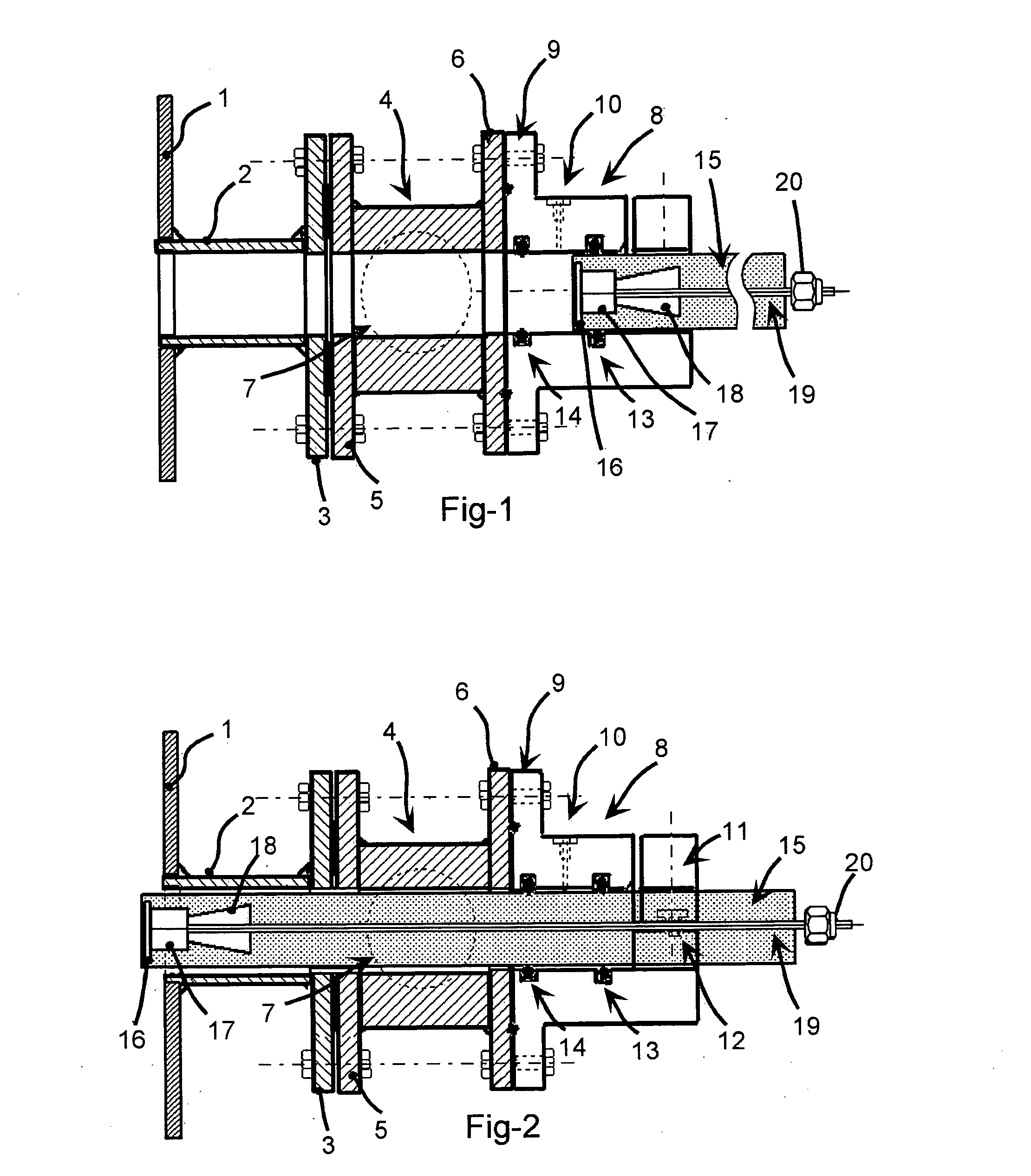
[0020]FIGS. 1 and 2 show a transformer tank 1 containing oil (not shown), said tank 1 having a channel 2 welded to its outside wall, the channel supporting a flange 3 having an emptying valve 4 fixed thereto. The valve 4 has two flanges 5 and 6 welded to each of its ends, respectively, the flange 5 being connected in leaktight manner to the flange 3 of the channel 2 by being fixed using peripheral bolts. In this example, the valve 4 has a ball plug 7 which is represented by dashed lines. Such an emptying valve is generally provided near the bottom of an oil-filled transformer tank in order to enable the oil to be removed therefrom when it needs to be changed, or when the transformer needs to be tested. A bushing 8 of generally cylindrical shape is situated in line with the valve 4 and includes a flange 9 at one of its ends. This flange is connected to the flange 6 of the valve 4 by means of a plurality of peripheral bolts each passing through both flanges 6 and 9.

[0021] The assembl...


PUM


Abstract

A sensor for picking up partial discharges in an electrical equipment tank filled with a dielectric fluid includes an antenna responsive to the electromagnetic waves generated by such partial discharges. In the sensor, the antenna is formed by two electrodes that are separated from each other by a dielectric resonator. With this arrangement, the sensor has improved sensitivity in the UHF range, while being of dimensions that are considerably smaller than dimensions of a conventional antenna for use in the UHF range.

Description

[0001] The invention relates to a sensor for detecting partial discharges in an electrical equipment tank filled with a dielectric fluid, the sensor comprising an antenna capable of picking up the electromagnetic waves generated by such partial discharges. BACKGROUND OF THE INVENTION [0002] These waves occupy a spread of frequencies extending from the high frequency range (HF) to the ultrahigh frequency range (UHF), the highest frequencies being capable of reaching approximately 2 gigahertz (GHz) if the dielectric fluid is a gas, and approximately 1.5 GHz if the fluid is a liquid. [0003] For several years, measurements have commonly been performed in the HF and very high frequency (VHF) frequency ranges to detect the impulses of partial electric discharges in electrical equipment installed in a casing filled with a dielectric fluid (a liquid or a gas), but that technique presents drawbacks. Corona discharges taking place in the vicinity of the equipment generate high intensity elect...

Claims


Application Information

Patent Timeline
IPC IPC(8): G01R31/08G01R31/06G01R31/12G01R31/16
CPCG01R31/16G01R31/1272
Inventor RAJA, KUPPUSWAMY
Owner ALSTOM TECH LTD
Why Eureka
Try Eureka