Method and the plasma display panel with an improvement of overflow effect of anisotropic conductive adhesive film
a technology of anisotropic conductive adhesive film and plasma display panel, which is applied in the direction of optics, instruments, printed circuit aspects, etc., can solve the problems of silver electrode migration, silver electrode exposed, and reduce so as to prolong the life of the plasma display panel
- Summary
- Abstract
- Description
- Claims
- Application Information
AI Technical Summary
Benefits of technology
Problems solved by technology
Method used
Image

Examples
first embodiment
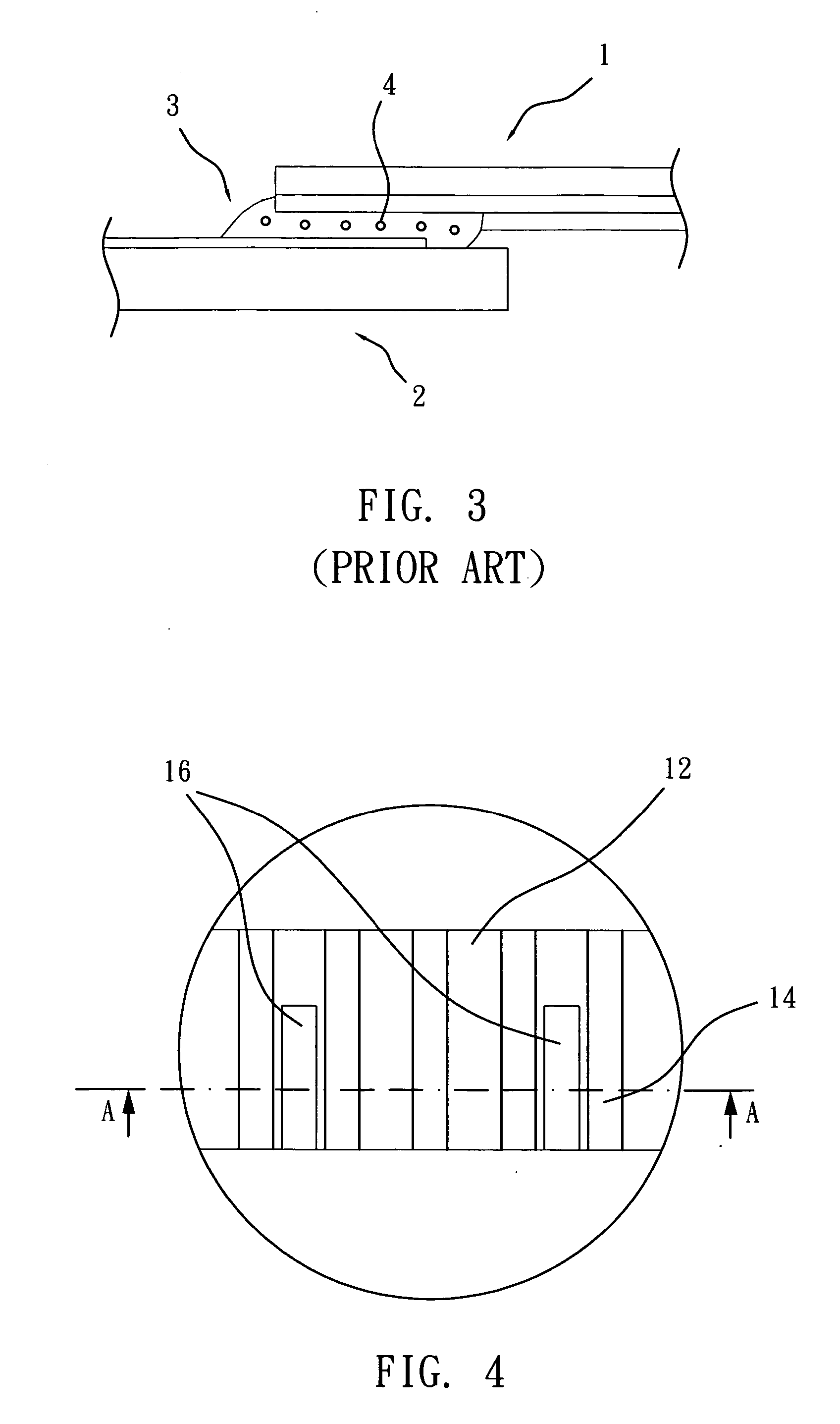
[0023] As shown in FIG. 4 and FIG. 5, a method of the first preferred embodiment comprises the steps of that provides a plurality of parallel guide blocks 16 on a panel 12 between silver electrodes 14, such as address electrodes. The guide blocks 16 are elongated walls printed on between the silver electrodes 14 with a predetermined thickness and length respectively. The elongated orientations of the guide blocks 16 are parallel to axes of the silver electrodes 14 respectively.
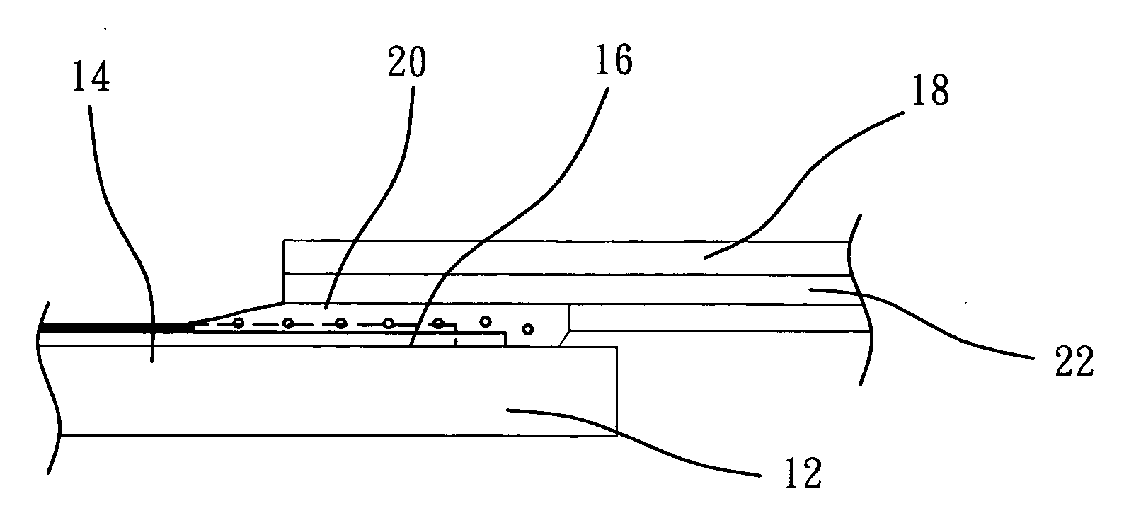
[0024] As shown in FIG. 6, processing a bonding process of a flexible printing circuit (FPC) 18. The bonding process has the steps of that place an anisotropic conductive film 20 between the silver electrodes 14 of the panel 12 and the electrodes 22 of the flexible printing circuit (FPC) 18. (The electrodes 22 are a gold-plated copper electrode. In addition, the electrodes of the roll flexible printing circuit (FPC) are a solder plated copper electrode.) Use hot bond to melt an anisotropic conductive film 20,...
second embodiment
[0026] As shown in FIG. 8 and FIG. 9, the second preferred embodiment provides guide blocks 30 on electrodes 34 of a flexible printing circuit (FPC) 32 and elongated orientations of the guide blocks 30 are parallel to silver electrodes of a panel (not shown).
[0027] Therefore, while hot bonding an anisotropic conductive film, it still can cover the silver electrodes of a panel and serve the function as same as the first preferred embodiment.
third embodiment
[0028] As shown in FIG. 10, a method of the third preferred embodiment provides guide blocks 48 between silver electrodes 42 on a panel 40 and guide blocks 49 on a flexible printing circuit (FPC) 44 respectively to guide the flow of a melted conductive film 46. It also has the functions of protecting the silver electrodes 42 and prolonging the life of the plasma display panel (PDP).
[0029] In conclusion, the present invention provides the method applied to the backend process of the plasma display panel (PDP). The method uses the overflow of the conductive film after the bonding process and provides the guide blocks between silver electrodes on the panel or on the electrodes of the flexible printing circuit (FPC) or on both of them to guide the flow of the overflow of the conductive film to cover the silver electrodes. This will protect the silver electrodes of the panel and prolong the life of the plasma display panel (PDP).
[0030] The guide blocks of the present invention should n...
PUM
 Abstract
Description
Claims
Application Information
 - R&D
- Intellectual Property
- Life Sciences
- Materials
- Tech Scout
- Unparalleled Data Quality
- Higher Quality Content
- 60% Fewer Hallucinations
Browse by: Latest US Patents, China's latest patents, Technical Efficacy Thesaurus, Application Domain, Technology Topic, Popular Technical Reports.
© 2025 PatSnap. All rights reserved.Legal|Privacy policy|Modern Slavery Act Transparency Statement|Sitemap|About US| Contact US: help@patsnap.com