
Heat dissipation module

Inactive Publication Date: 2006-07-06
COMPAL ELECTRONICS INC
View PDF4 Cites 12 Cited by
  • Summary
  • Abstract
  • Description
  • Claims
  • Application Information

AI Technical Summary

Benefits of technology

[0013] In view of this, an objective of the invention is to provide a heat dissipation module which is suited for portable electronic device. This can let the portable electronic device not only satisfy the safety standard but also improve its heat dissipation efficiency.
[0014] Another objective of the invention is to provide a heat dissipation module suited for portable electronic device to reduce its production cost.
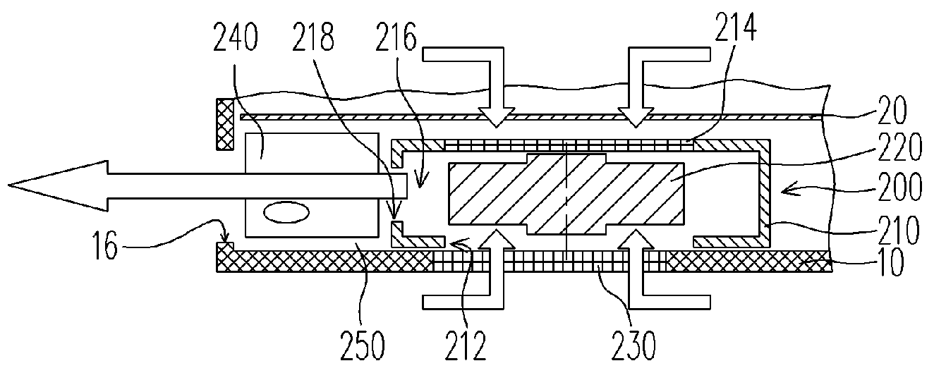
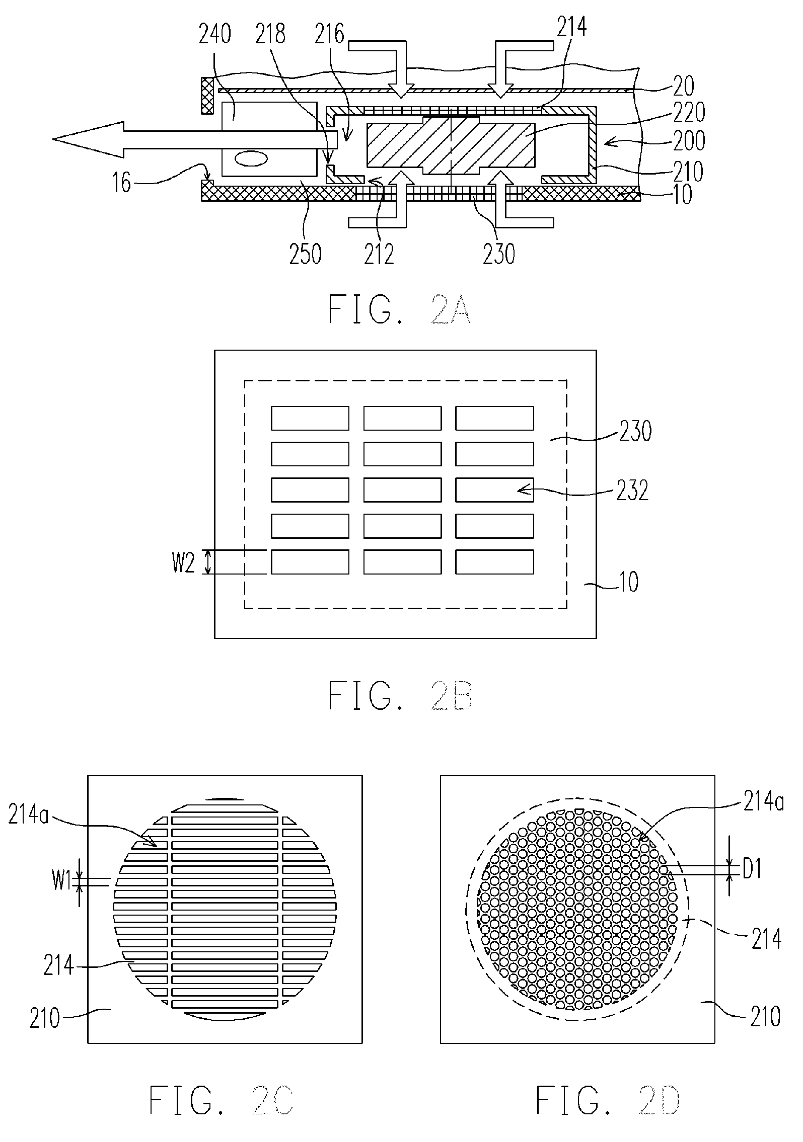
[0021] As mentioned above, the invention of the heat dissipation module is to install a second mesh, which satisfies the safety standard, at the top of the housing. And a first mesh is installed at the bottom of the casing of the portable electronic device, wherein the first mesh does not need to satisfy the size restriction of the safety standard. Thus the width or diameter of these holes on the first mesh can be relatively greater than those on the second mesh. This can allow the portable electronic device not only to satisfy the safety standard but also to enhance its heat dissipation efficiency. In addition, the first mesh and the second mesh are respectively formed together with the bottom of the casing and the top of the housing as an integral unit to reduce the production cost of the portable electronic device.

Problems solved by technology

Due to the restriction in the dimension of the notebook, it causes the inner space of the notebook to be narrow.
Consequently, the heat dissipation effect of the portable electronic device can not be improved.
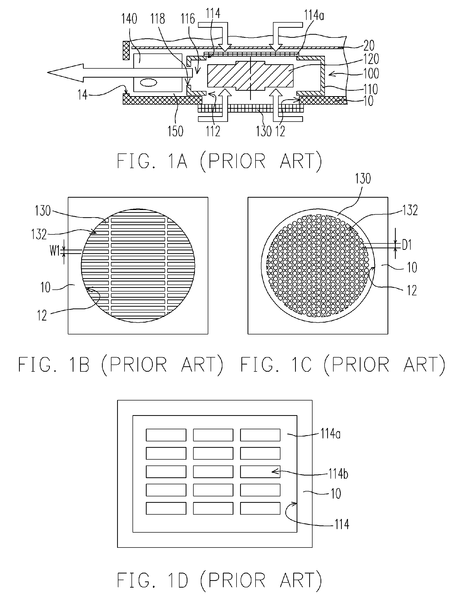
However, since the second air inlet 114 is located at the top of the housing 110 and is close to the inner part of the portable electronic device, its ability to engulf intake airflow for the portable electronic device is limited.
However, this will cause that the integral formation method cannot be used to directly form the mesh 130 on the casing 10 of the portable electronic device.
Therefore the production cost of the portable electronic device cannot be decreased.
Also, even though the number of these openings 132 increases, there is still not able to have enough intake airflow to the portable electronic device due to the restriction of the safety standard, causing the width W1 or diameter D1 of these openings to be too small.
Similarly, the heat dissipation efficiency of the portable electronic device can not be improved.

Method used


Image

  • Heat dissipation module
  • Heat dissipation module
  • Heat dissipation module

Examples


Embodiment Construction

[0031] Referring to FIG. 2A, it is a cross-sectional drawing, schematically illustrating a heat dissipation module suited for a portable electronic device, according to a preferred embodiment of the invention. The heat dissipation module 200 is suited for a portable electronic device, such as notebook. This portable electronic device includes a main module (not shown) and a casing 10. The main module has a motherboard 20 which is installed in the casing 10. In addition, the casing 10 has an opening 16 which is at lateral location of the casing 10 to lead the air out.

[0032] The aforementioned heat dissipation module 200 includes a housing 210 and a fan 220, wherein the fan 220 is installed inside the housing 210. The rotation axis direction of the fan 220 is substantially parallel to the center axis of the air inlet 212 of the housing 210 and the second mesh 214, and substantially perpendicular to the center axis of the air outlet 218.

[0033] In addition, referring to FIG. 2A and 2B...


PUM


Abstract

A heat dissipation module is suited for a portable electronic device. The module includes a first mesh, a housing and a fan, wherein the first mesh disposed at the bottom of the casing of the device has a plurality of first openings. The housing has an air inlet, a second mesh, a mounting space and an air outlet, wherein the second mesh disposed at the top of the housing has a plurality of second openings. The diameter of each of the second openings is smaller than that of the first openings. To satisfy the safety standard, the heat dissipation efficiency of this device can be improved by changing the size of these two openings. Furthermore, the first and second mesh are respectively formed with the bottom of the casing and the top of the housing together as an integral unit to reduce the production cost of the portable electronic device.

Description

CROSS-REFERENCE TO RELATED APPLICATION [0001] This application claims the priority benefit of Taiwan application serial no. 94200020, filed on Jan. 3, 2005. All disclosure of the Taiwan application is incorporated herein by reference. BACKGROUND OF THE INVENTION [0002] 1. Field of Invention [0003] The present invention relates to heat dissipation module, and specifically to the heat dissipation module with mesh, which is suited for portable electronic device and used to provide heat dissipation function to the portable electronic device. [0004] 2. Description of Related Art [0005] In recent years, computer technology has been greatly and fast improved. In addition to the operation speed of the computer advancing continuously, the heat energy of electronic component of the computer also constantly increases. In order to prevent overheating of the electronic components in the computer, which causes the temporary or permanent malfunction of the electronic component, the common technolo...

Claims


Application Information

Patent Timeline
IPC IPC(8): G06F1/20H01L23/467H05K7/20
CPCG06F1/203H01L23/467H01L2924/0002H01L2924/00
Inventor WANG, HSUAN-CHENGLIN, CHUN-HUNG
Owner COMPAL ELECTRONICS INC
Learn More