Packet transfer control method and packet transfer control circuit

a control circuit and control method technology, applied in the field of packet transfer control methods and packet transfer control circuits, can solve the problems of deteriorating communication quality for users, affecting the scalability of hardware quantity and scheduler process load, and not ensuring communication quality prevails

Inactive Publication Date: 2006-07-06
PANASONIC CORP
View PDF16 Cites 26 Cited by
  • Summary
  • Abstract
  • Description
  • Claims
  • Application Information

AI Technical Summary

Benefits of technology

[0011] Thereby, band control and priority control of packet output, in which class setting of each flow is performed according to the band that each flow uses, and packets belonging to each flow are output based on this set class can be realized by a simple hardware configuration.
[0019] Thereby, management is enabled so that order of packets is maintained and packets are accurately processed at the destination thereof.
[0025] Thereby, band control and priority control of packet output, in which class setting for each flow is performed according to the band that each flow uses, and packets belonging to each flow are output based on this set class can be realized by a simple hardware configuration.
[0033] Thereby, management is enabled so that order of packets is maintained and packets are accurately processed at the destination thereof.

Problems solved by technology

Currently, in networks such as Internet, best effort service, which does not guarantee communication quality prevails.
Along with increase of traffic and appearance of services to require different communication qualities, deterioration of communication quality for users has become a problem.
Moreover, when many flows are dealt in the high-speed communication line as above, if QoS control is made by scheduling having a queue for every flow such as WRR (Weighted Round Robin), it becomes difficult to obtain scalability for both hardware quantity and scheduler process load.
As above, when all the flows, in which various types of packets are mixed are stored and controlled in one queue, performing QoS guarantee according to communication quality required for each of various types of packets in each flow is not possible.
However, some users allow small minimum guaranteed band, but demands a large region of sending to the excess band, a so-called best effort.
It is not possible to satisfy such a demand only by allocating the excess band in proportion to the minimum guaranteed band.

Method used


Image

  • Packet transfer control method and packet transfer control circuit
  • Packet transfer control method and packet transfer control circuit
  • Packet transfer control method and packet transfer control circuit

Examples


first embodiment

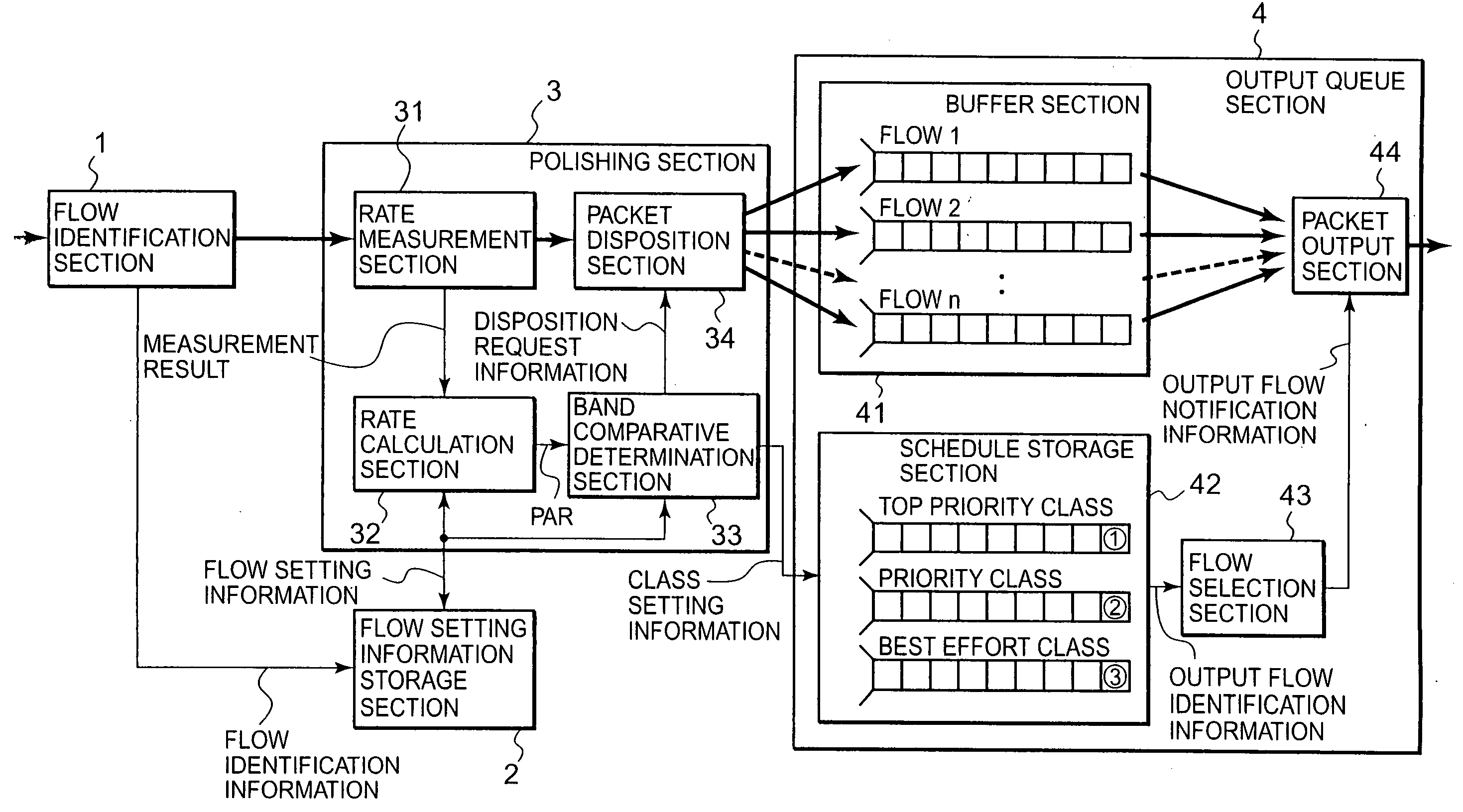
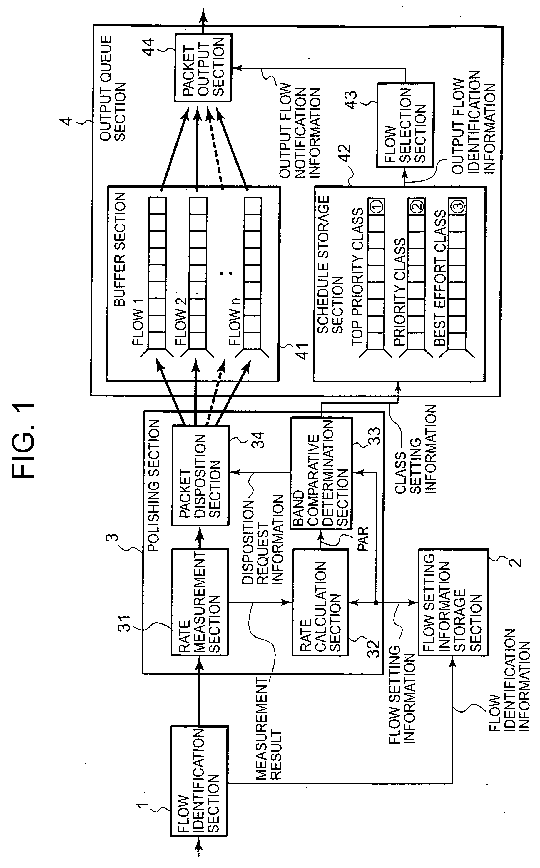
[0047] First, a first embodiment of the packet transfer control method and the packet transfer control circuit of the invention will be described. FIG. 1 is a block diagram showing a construction example of a packet transfer controller in the first embodiment of the invention. The packet transfer controller shown in FIG. 1 includes a flow identification section 1, a flow setting information storage section 2, a polishing section 3, and an output queue section 4. In FIG. 1, flow of packet is indicated by heavy lines, and flow of other information is indicated by thin lines.

[0048] The flow identification section 1 is provided with a packet sent from, for example, a communication terminal accommodated in a given communication network. The flow identification section 1 refers to header information of the provided packet (input packet), identifies the flow, to which the input packet belongs, and notifies information for the result of flow identification (flow identification information)...

second embodiment

[0076] Next, a second embodiment of the packet transfer control method and the packet transfer control circuit of the invention will be described. FIG. 5 is a block diagram showing a construction example of a packet transfer controller in the second embodiment of the invention. The packet transfer controller shown in FIG. 5 is a packet transfer controller, in which a band control function for every group is further added to the packet transfer controller shown in FIG. 1. Specifically, in the packet transfer controller shown in FIG. 5, a group setting information storage section 5 for storing information for each group (group setting information) is further provided. Further, in a rate calculation section 52 and a band comparative determination section 53, functions for performing processes about a packet arrival rate for every group (in some cases, hereinafter simply referred to as GPAR: Group Packet Arrival Rate) or upper limit band information for every group (in some cases, herei...


PUM


Abstract

Band control for every flow is made, and at the same time priority control is realized by a simple hardware configuration. A flow identification section 1 identifies the flow, to which each packet belongs. Flow identification information is notified to a flow setting information storage section 2. Based on such information, flow setting information is notified to a polishing section 3. In the polishing section, a rate measurement section 31 measures an arrival rate of the packet, and based on this arrival rate, a rate calculation section 32 calculates an arrival rate for the flow, to which the packet belongs. Then, a band comparative determination section 33 compares this arrival rate for the flow to information such as the minimum guaranteed band and the upper limit band previously set for this flow, and performs class setting for the flow for every packet. Flow identification information for each flow is stored in a schedule storage section 42 by class. A flow selection section 43 and a packet output section 44 selectively outputs the flow belonging to the high priority class.

Description

TECHNICAL FIELD [0001] The present invention relates to a packet transfer control method and a packet transfer control circuit for controlling output order of packets when a plurality of provided packets are selectively output to the output line, and particularly to a packet transfer control method and a packet transfer control circuit according to band control method for performing band guarantee for each flow. BACKGROUND ART [0002] In recent years, ADSL (Asymmetric Digital Subscriber Line) and FTTH (Fiber To The Home) have become popular. Therefore, always-on connections service in the consumer market has been popularized, and broadbandalization of access networks has become accelerated. Further, along with development of consumer electronics (home information appliances) corresponding to computerization and popularization of digital image delivery service, it is expected that differentiation demand for communication quality corresponding to various communication services would be...

Claims


Application Information

Patent Timeline
Patent Type & Authority Applications(United States)
IPC IPC(8): H04L12/26H04L12/56H04L47/20H04L47/32H04L47/6275
CPCH04L47/10H04L47/2416H04L47/2441H04L47/2483
Inventor KANAZAWA, TAKESHI
Owner PANASONIC CORP
Why Eureka
Try Eureka