
Microdosing apparatus and method for dosed dispensing of liquids

a micro-dosing apparatus and liquid technology, applied in the direction of pump control, spray nozzle, positive displacement liquid engine, etc., can solve the problem of requiring a comparatively complex micro device, and achieve the effect of simple structure and easy change of the dosing volum

Active Publication Date: 2006-07-06
BIOFLUIDIX
View PDF7 Cites 51 Cited by
  • Summary
  • Abstract
  • Description
  • Claims
  • Application Information

AI Technical Summary

Benefits of technology

"The present invention provides a microdosing apparatus with a simple structure that allows for easy change of the dosing volume by adjusting the hub of the actuating device or the position of the actuating device along the fluid conduit. This allows for easy adjustment of the dosing volume to dispense liquid as free flying droplets or as free flying jet. The apparatus includes a flexible tube with a first end for connecting to a liquid reservoir and a second end where an outlet opening is located. The apparatus also includes an actuating device disposed at a predetermined position along the fluid conduit, which can be adjusted to change the volume of the fluid conduit and thus the dosing volume. The invention provides a method for dosed dispensing of liquids using the microdosing apparatus. The invention allows for easy adjustment of the dosing volume and provides a more efficient and cost-effective solution for dosed dispensing of liquids."

Problems solved by technology

However, this method requires a comparatively complex micro device.

Method used


Image

  • Microdosing apparatus and method for dosed dispensing of liquids
  • Microdosing apparatus and method for dosed dispensing of liquids
  • Microdosing apparatus and method for dosed dispensing of liquids

Examples


Embodiment Construction

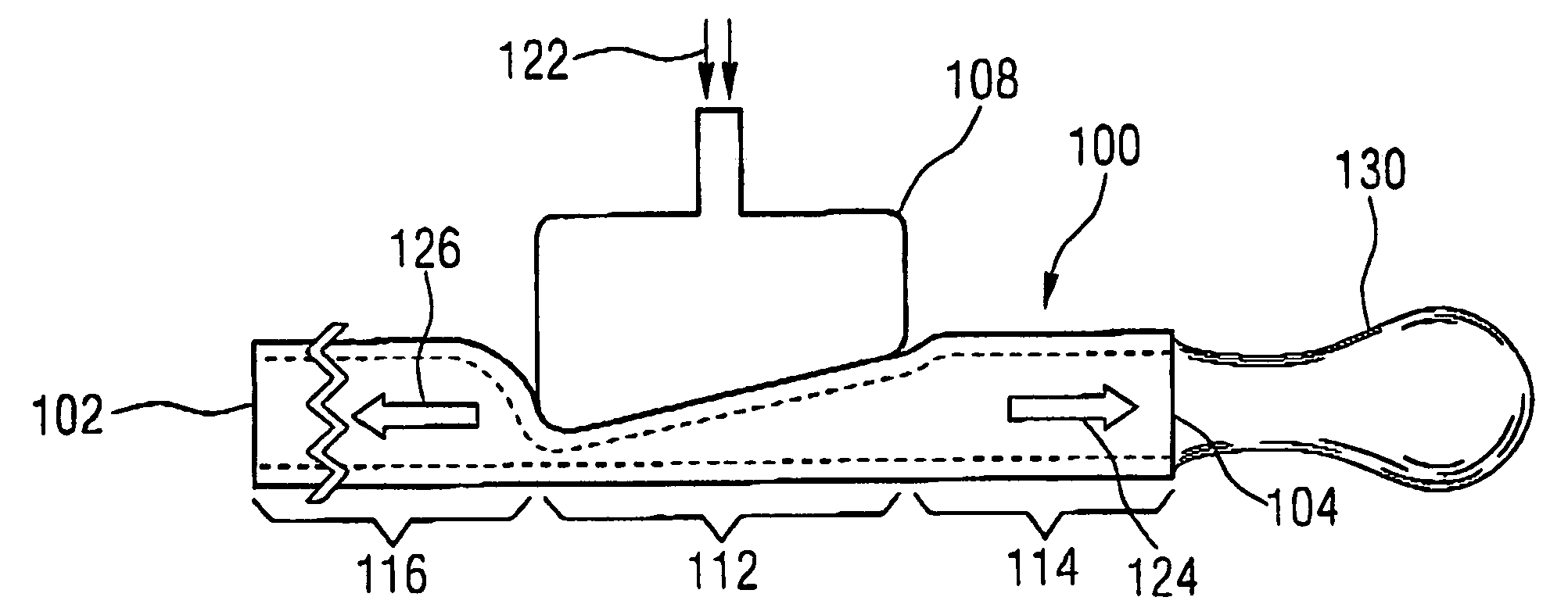
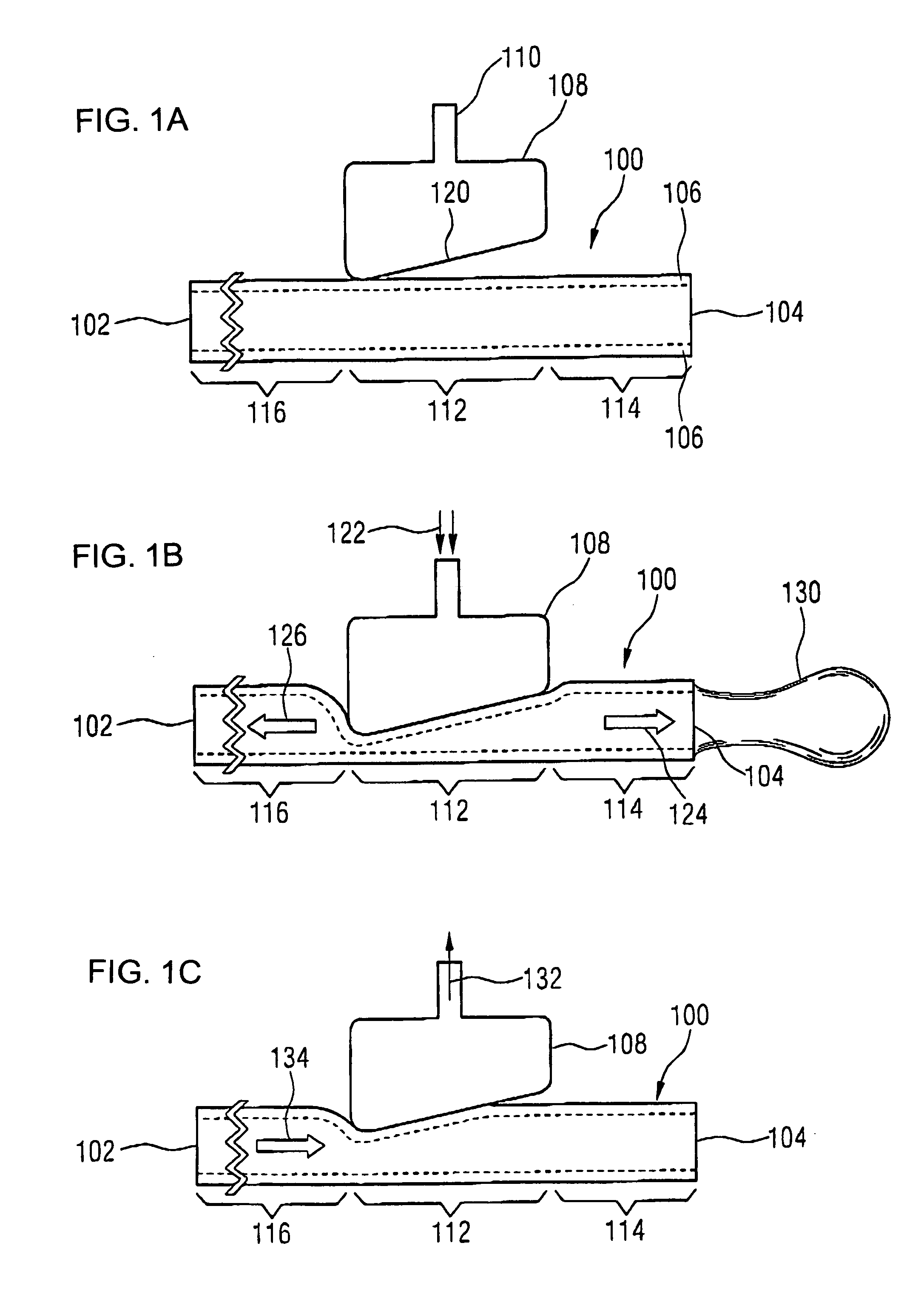
[0046] With regard to the schematic representations in FIGS. 1a to 1c, the essential features of the present invention as well as the concept underlying the same will be discussed below.

[0047] The present invention relates to an apparatus or a method, respectively, for generating microdrops or microjets, respectively, mainly in the nanoliter to picoliter range. A fluid carrying conduit is a central element of an inventive microdosing apparatus, whose inlet opening is connected to a liquid reservoir, in which the media to be dosed is located. On the other end of the conduit is an outlet opening through which the liquid to be dosed can be dispensed. The fluid carrying conduit is preferably mainly made of an elastic material, so that the volume of the conduit between inlet opening and outlet opening can be varied by deforming the conduit, for example compressing the same.

[0048] The essential elements of an inventive dosing apparatus during different phases of a dosing process are sho...


PUM


Abstract

A microdosing apparatus comprises a fluid conduit having a flexible tube with a first end for connecting to a fluid reservoir and a second end where an outlet opening is located. An actuating device with a displacer with adjustable hub is provided, by which the volume of a portion of the flexible hub can be changed to thereby dispense liquid as free flying droplets or as free flying jet at the outlet opening by moving the displacer between a first end position and a second end position, whereby the tube is partly compressed in the first or the second end position. In other words, a microdosing apparatus comprises fluid conduit having a portion along which a cross section of the fluid conduit is variable by an actuating device to effect a change of the volume of the fluid conduit. A ratio of a fluidic impedance between the position of the actuating device and the outlet opening to a fluidic impedance between a first end of the fluid conduit and the position of the actuating device is variable by changing the position of the actuating device, so that a dosing volume dispensed at the outlet opening is variable thereby by at least 10%.

Description

CROSS-REFERENCE TO RELATED APPLICATIONS [0001] This is a continuing application, under 35 U.S.C. §120, of copending international application PCT / EP2004 / 009063, filed Aug. 12, 2004, which designated the United States; this application also claims the priority, under 35 U.S.C. §119, of German patent application DE 103 37 484.1, filed Aug. 14, 2003; the prior applications are herewith incorporated by reference in their entirety.BACKGROUND OF THE INVENTION [0002] 1. Field of the Invention [0003] The present invention relates to a microdosing apparatus, to methods for dosed dispensing of liquids and to methods for adjusting a desired dosing volume range when using an inventive microdosing apparatus. [0004] 2. Description of the Related Art [0005] According to the prior art, volumes in the nanoliter range (10−12 m3) are not dosed with conventional pipettes, but require specific methods to ensure the required precision. [0006] Here, in addition to contact methods, conventional dispensing ...

Claims


Application Information

Patent Timeline
Patent Type & Authority Applications(United States)
IPC IPC(8): F04B49/06F04B17/00F04B43/12B01L3/02
CPCB01L3/0268B01L2300/0838B01L2300/123B01L2400/0481Y10S239/12
Inventor ZENGERLE, ROLANDKOLTAY, PETERSTREULE, WOLFGANGBIRKLE, GERHARD
Owner BIOFLUIDIX
Learn More