
Method for the production of a structural part comprising a rigid material and a plastic material, and structural composite part thus obtained

a technology of rigid materials and composite structural parts, which is applied in the field of manufacturing a composite structural part of a rigid material and a plastic material, can solve the problems of separating plastic parts, needing to produce, store and handle plastic material parts separately, and connecting both parts of different materials, etc., to achieve convenient recycling and easy operation.

Inactive Publication Date: 2006-07-06
SINTEX BETEILINGUNGS
View PDF7 Cites 35 Cited by
  • Summary
  • Abstract
  • Description
  • Claims
  • Application Information

AI Technical Summary

Benefits of technology

"The present invention provides a process for manufacturing a composite structural part of a rigid material and a plastic material. The process involves forming a plate part of rigid material with a hole and arranging a plastic injection mold around the plate part. Plastic material is then injected into the mold to fill the holes. The plastic material is deformed by heat and pressure to form a fixing head, which is connected to the plate part through the hole. The fixing head has a grip configuration that can be engaged by an actuation tool for applying a torque to separate the rigid material and the plastic material. The composite structural part has the advantage of being recyclable at the end of its useful life."

Problems solved by technology

The issue is how to connect both parts of different materials.
The main drawback of the method disclosed above is that the separated plastic part needs to have a structural consistency that is sufficient for allowing the part to be handled without it becoming permanently deformed.
Another drawback is the need to produce, store and handle the plastic material parts separately from the production, storage and handling of the rigid material parts.
This method, however, has the same drawbacks mentioned above, and furthermore, if it is used to incorporate reinforcing ribs to a metal plate part, said ribs must have a specific design reinforced to resist the buckling stress produced by the pressure exerted by the metal plate part during the process, generally leading to oversizing which also represents a waste of material plastic.
However, the connections provided by said connection heads are difficult to break when intending to separate the rigid material and plastic material components for recycling purposes.
If the simple system of pulling one component with regard to the other is attempted to be used in order to carry out said separation, this may cause the breakage of the weaker component, i.e. that of the synthetic material, in unwanted areas, leaving smaller or larger pieces of synthetic material connected to the main body by the connection heads.
This forces carrying out the separation of the components by means of a much more complex and costly system consisting of grinding the composite part into small pieces and then separating the pieces according to the different properties of the materials, for example, by gravity, by blowing, by magnetic attraction, etc.

Method used


Image

  • Method for the production of a structural part comprising a rigid material and a plastic material, and structural composite part thus obtained
  • Method for the production of a structural part comprising a rigid material and a plastic material, and structural composite part thus obtained
  • Method for the production of a structural part comprising a rigid material and a plastic material, and structural composite part thus obtained

Examples


Embodiment Construction

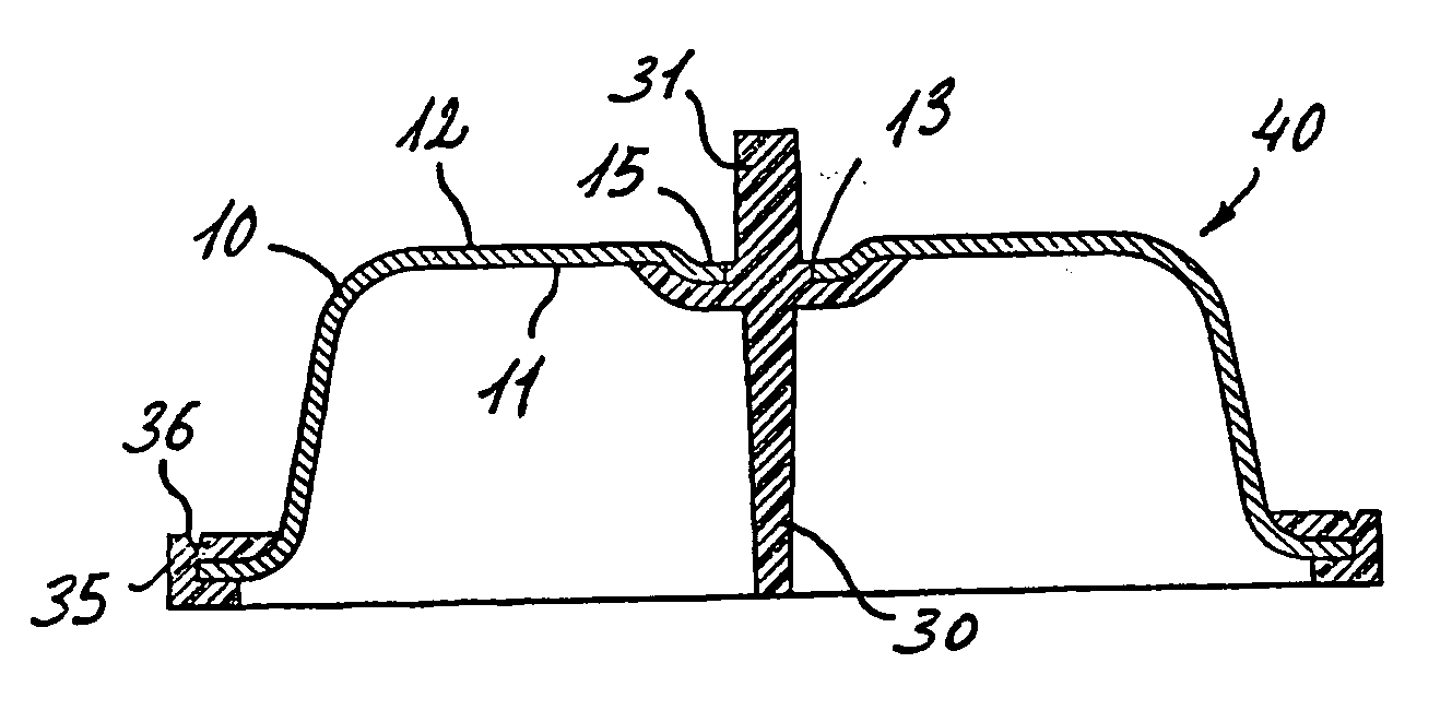
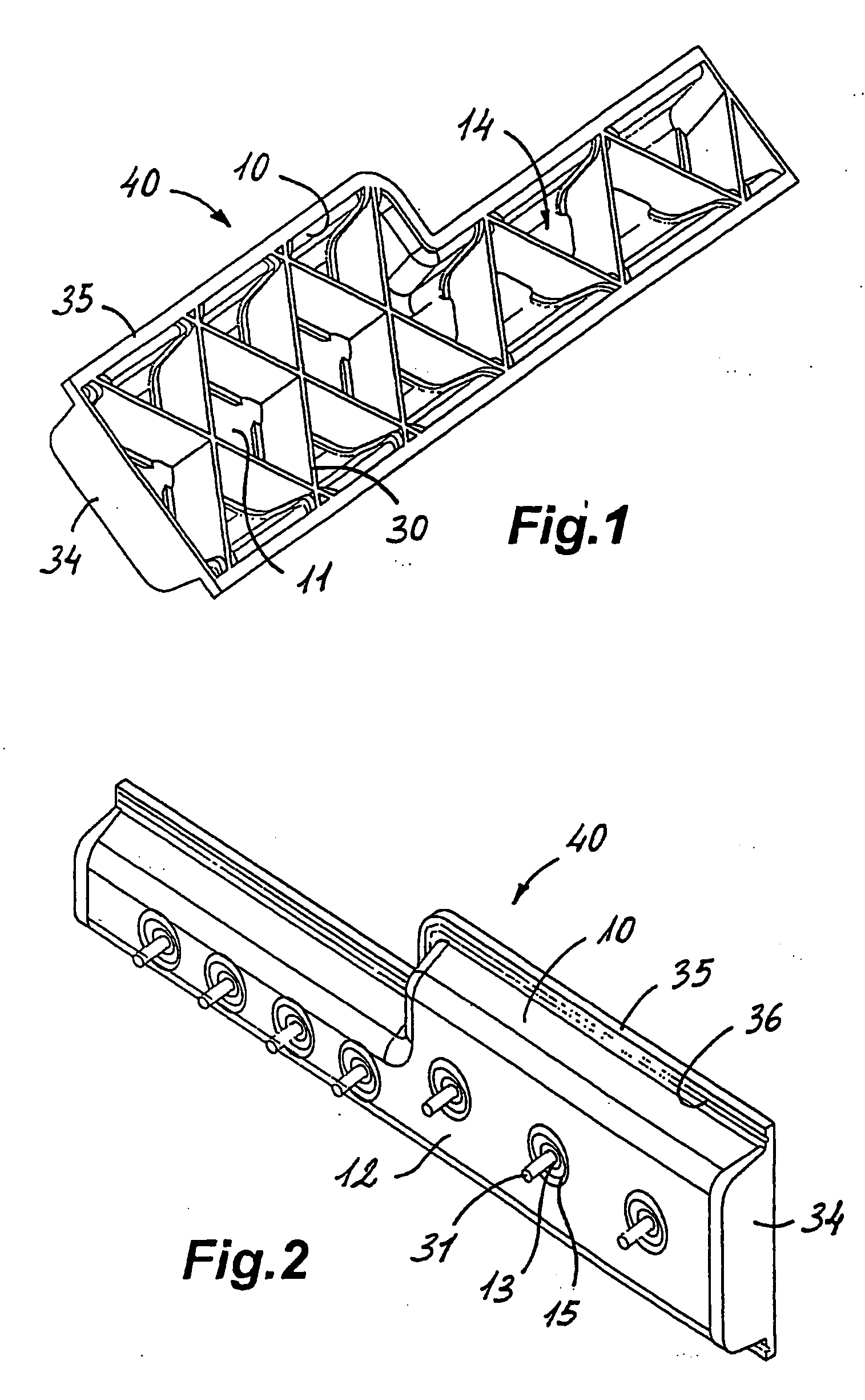
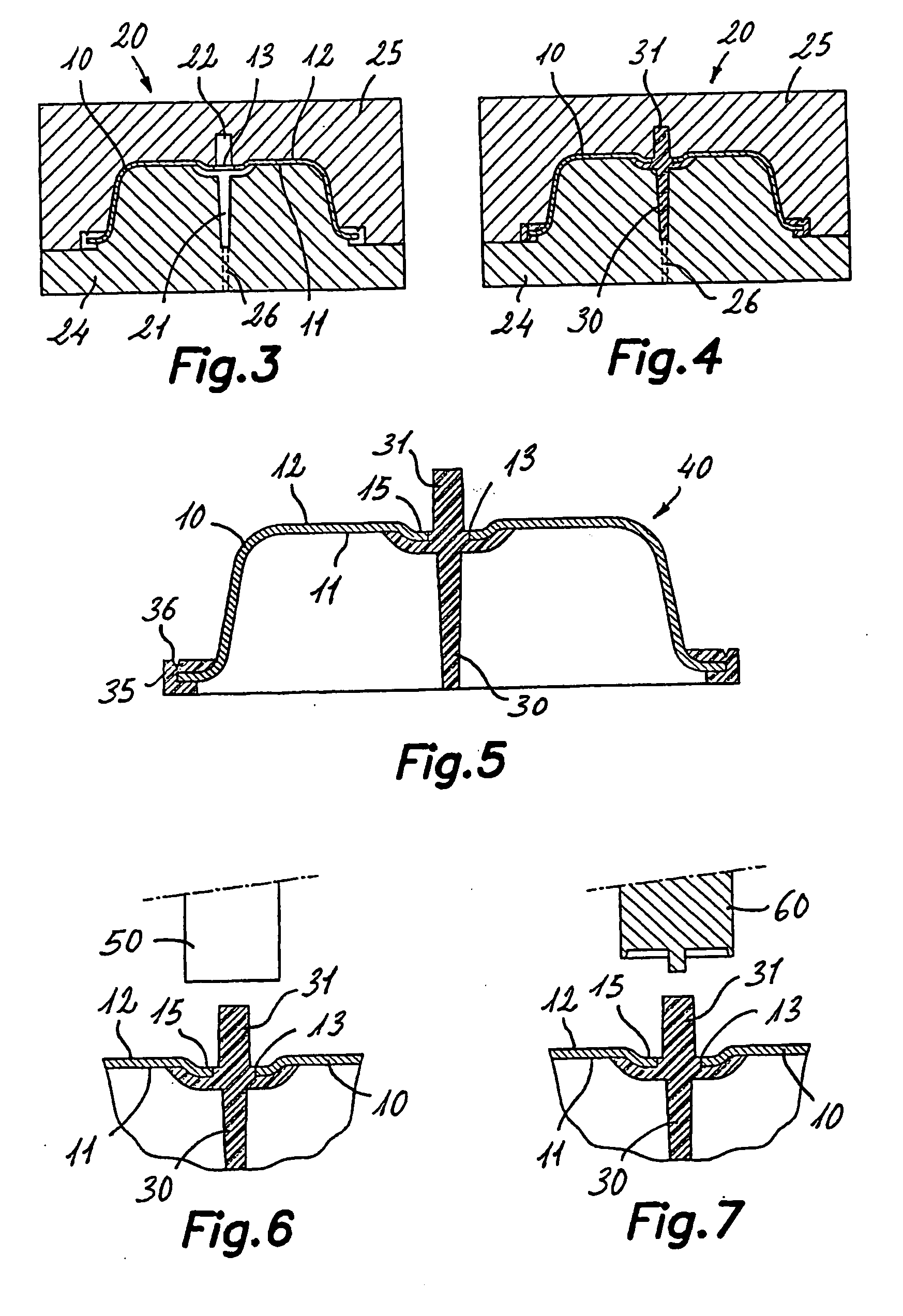
[0035] First in reference to FIG. 1, the composite structural part of a rigid material and a plastic material is generally designated with reference number 40, and it comprises a plate part 10 of a rigid material, formed by means of a deep-drawing process, whereby it generally comprises a concavity 14 next to a first inner side 11, and a second convex side 12. A series of holes 13 (FIG. 2) extend between said first and second sides 11, 12. Advantageously, depressed areas 15 are formed around the holes 13 in the second side 12 of the plate part 10. Housed inside said cavity 14 are a plurality of reinforcing ribs 30 of plastic material formed by injection on said first side 11 of the plate part 10. Said reinforcing ribs 30 are relatively thin and form a framework designed to provide desired rigidity and strength to the plate part 10, which is also relatively thin. To that end, the reinforcing ribs 30 are connected to the plate part 10 at different discrete connection points by means o...


PUM

PropertyMeasurementUnit
flexural breaking strengthaaaaaaaaaa

Abstract

The process comprises injecting a melted plastic material into a mold in which a plate part (10) is arranged with at least one hole (13) inter-placed between first and second cavities (21, 22), then withdrawing the plate part (10) from the mold with at least one reinforcing rib (30) of plastic material adjacent one side (11), and at least a projection integral to the rib (30), projecting on the other side (12) through the hole (13), and finally deforming said projection by application of heat and pressure to form a fixing head (32) with a grip configuration (33). The composite structural part is integrated by the plate part (10) and the reinforcing rib (30) firmly connected thereto by means of said fixing head (32).

Description

FIELD OF THE INVENTION [0001] The present invention relates to a process for manufacturing a composite structural part of a rigid material and a plastic material, and more specifically to a process comprising a molding of a plastic material portion on a rigid material portion and a subsequent consolidation of the connection of both parts by application of heat and pressure. The present invention also relates to a composite structural part of a rigid material and a plastic material susceptible of being obtained by such process. [0002] The invention is useful for manufacturing light-weight resistant components and is applicable in industrial fields such as the manufacture of automobiles, household appliances, office machinery, furniture, light-weight structures, decoration, among others. TECHNICAL BACKGROUND [0003] It has been found that light-weight structural elements, with a relatively high strength and controlled deformation capacity, can be obtained from the combination of one pa...

Claims


Application Information

Patent Timeline
Patent Type & Authority Applications(United States)
IPC IPC(8): B32B3/10B29C45/14B29C45/00B29C65/60B29C65/76B29C67/00B29C69/00B29C70/74B62D29/00
CPCB29C45/0053Y10T428/24322B29C45/14311B29C45/14344B29C45/14778B29C65/06B29C65/08B29C65/10B29C65/606B29C65/607B29C65/76B29C66/81429B29C66/8322B29C67/0044B29C70/74B29C2045/14327B29C2045/14442B29K2705/00B29L2031/30B29L2031/3002B62D29/001B62D29/004B29C65/14B29C66/545B29C45/0055B29C66/12441B29C66/71B29C66/7392B29K2023/12B29K2077/00
Inventor RUIZ, RAFAEL
Owner SINTEX BETEILINGUNGS
Learn More