Safety trocar assembly

a trocar and safety technology, applied in the field of safety trocar assembly, can solve the problems all known solutions do not eliminate the problem of internal organ injury, and the insertion of the trocar into the body cavity can be accompanied, so as to reduce the resistance of body tissue, facilitate the passage of the trocar through the body cavity wall, and reduce the injury of the body cavity wall

Inactive Publication Date: 2006-07-06
POPOV
View PDF10 Cites 11 Cited by
  • Summary
  • Abstract
  • Description
  • Claims
  • Application Information

AI Technical Summary

Benefits of technology

[0011] Another invention objective is increased reliability of protector operation by preventing jamming and engagement of body cavity wall tissues between the members of trocar distal edge.
[0014] Another invention objective is decreased material consumption for the device, design simplification and device low-cost manufacturing.
[0017] The above noted objectives are accomplished by a safety trocar assembly having a portal unit with elongated obturator removably inserted through the cannula and having a handle on its proximal end and a penetrating end on its distal end. The penetrating end is exposed through the cannula open distal end and has a cutting means, a penetrating apex, and a sloping side wall immovable relative to obturator. The obturator is provided with a protector mean as having a bias means and a movable penetrating apex shield that in its retracted position opens the penetrating apex and in its extended position closes the penetrating apex preventing it from any contact with patient's organs. In the projection onto transverse plane, the obturator sloping side wall surrounds the penetrating apex shield. It means that the penetrating and, consequently, also the penetrating apex shield have little cross section dimensions in comparison with the obturator. This allows reduction of the resistance of body tissue during penetrating apex shield displacement to its extended position and provides fast acting protection of the penetrating apex immediately after the penetration of penetrating apex distal end into the body cavity, however, before the penetrating end has been fully inserted. Further dilation of the orifice in the body wall is carried out by cutting means located on the sloping side wall. The penetrating apex shield is made tubular of circular or flattened cross section, totally closed or having a slot on one side. The distal edge of this shield forms a fence precluding the introduction, jamming; and engagement of tissue fibers of the body cavity wall between the penetrating apex shield and the penetrating apex as well as between the penetrating apex shield segments. As a result, the injury of body cavity wall is decreased and trocar passing through body cavity wall is facilitated.
[0018] The shield for protection of the cutting means is characterized by a local comparative height equal to the ratio of local maximal shield height to a local maximal shield width measured in the same local obturator transverse plane. This parameter characterizes such properties of the protector shield as the resistance of body tissue to shield displacement to is extended (protected) position and velocity of this displacement. The less the value of this parameter the less the tissue resistance and the faster the shield displacement to extended position. According to the present invention, the shield, particularly made plate-shaped, has maximal value of the local comparative height less than 0.5. This shield is a low profile shield and the perimeter of its cross section insignificantly exceeds the perimeter of tissue incision made by the cutting means. Moreoever, the height of this plate-shaped shield (the plate thickness) amounts 0.4 to 2 mm for obturator with outer diameter 10 to 12.5 mm and 0.4 to 1.2 mm for obturator with outer diameter 5 to 6.5 mm. This shield is a fast acting protector entering the tissue incision without substantial resistance of tissue incision edges and enabling the shield entry the body cavity immediately after entry there the cutting means. As a result, the risk of patient internal organ injury is significantly decreased.
[0019] In version embodiment, a safety trocar assembly comprises a penetrating means with at least two penetrating zones and a protector means with independent protector members, made as shields, for independent protection of each of said penetrating zones, and a resilient bias means for each of the protector members. This protects the penetrating zone (knife) which enters the body cavity independently of another penetrating zones (knives) which have not yet entered the body cavity and continue to cut the tissue. In version embodiment, there are distal and proximal penetrating zones provided with a distal and a proximal independent shield, respectively. The distal penetrating zone is the first one that enters the body cavity and is a main cause of internal organ injury, so its independent and fast protection eliminates trocar procedure complications.
[0020] In version embodiment, the displacement of the proximal shield from the extended position to the retracted position demands greater force than identical displacement of the distal shield. That can be achieved by larger rigidity of the bias means (in the form of a spring) of the proximal shield than one of the distal shield. As a result, the proximal penetrating zone forms such final dimensions of orifice that is accurately adapted to the cannula outer diameter. Described penetrating and protector means have so simple a design (for example, making protector and biasing members as a one detail) so as to permit their arrangement in the limits of obturator distal part. Such implementation increases trocar reliability and reduces its manufacturing cost.

Problems solved by technology

Trocar insertion into body cavity can be accompanied with internal organ injury.
However, all known solutions do not eliminate the problem of internal organ injuries.
However, such mechanism leads to inevitable injury of body cavity wall, increased resistance to the device advance, the device advance in jerks, and high probability of protector jamming.
Further device advance is possible solely by rupturing these fibers which, in its turn, results in increased tissue injury and in the device hindered advance.
However, shield members have such sizes, shape, arrangement and contact zone with body cavity wall that they generate considerable resistance between the shield and the body cavity wall tissues, and the latter holds the shield in totally retracted position, up to the shield complete removal beyond the bounds of body cavity wall, which means that no successive protection of piercing-cutting members takes place as they enter the body cavity.
But tissue injury during the trocar performance remains considerable.

Method used


Image

  • Safety trocar assembly
  • Safety trocar assembly
  • Safety trocar assembly

Examples


Embodiment Construction

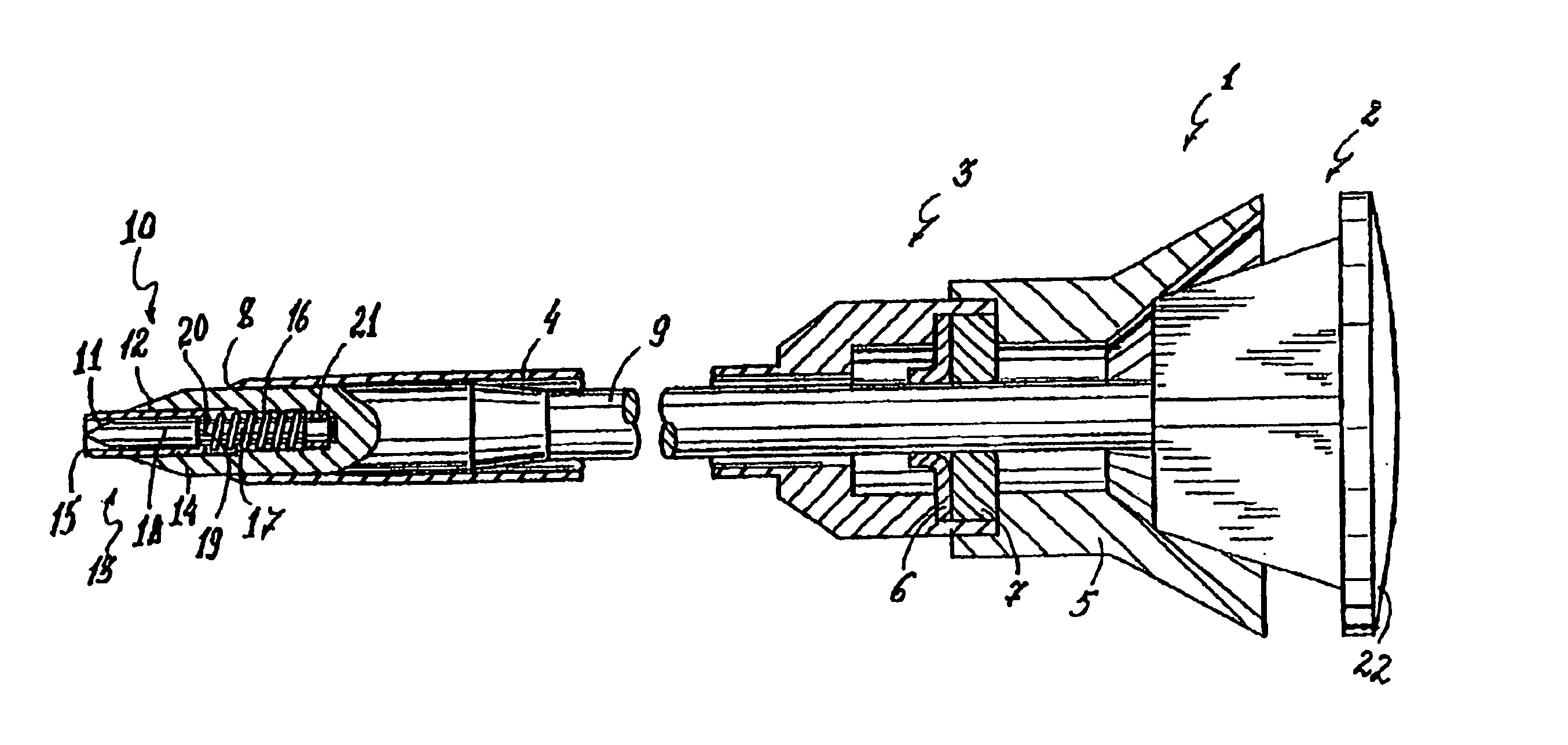
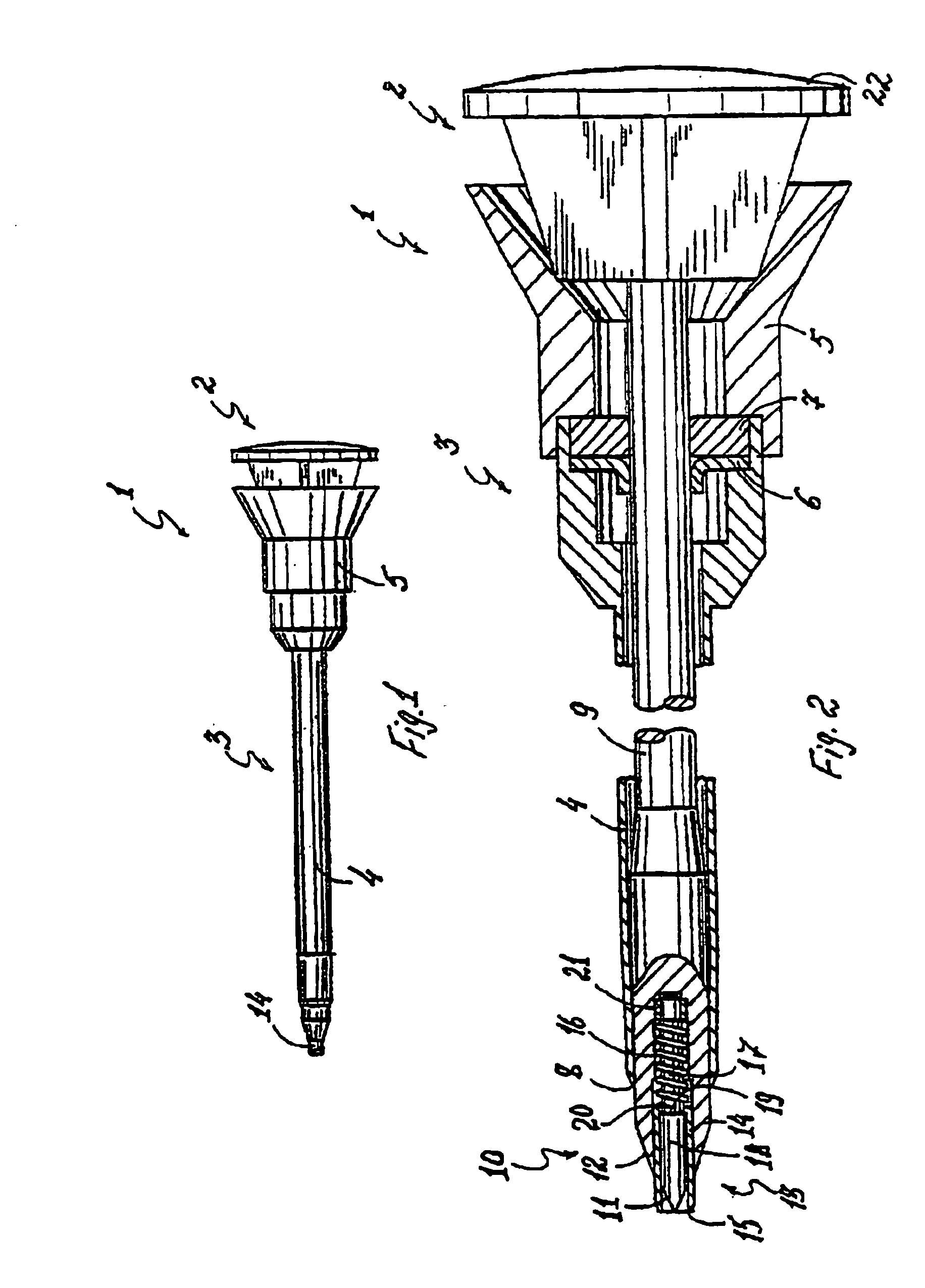
[0076] Safety trocar assembly is intended for making orifices in body cavity wall and generation of conditions for subsequent introduction of instruments into a body cavity.

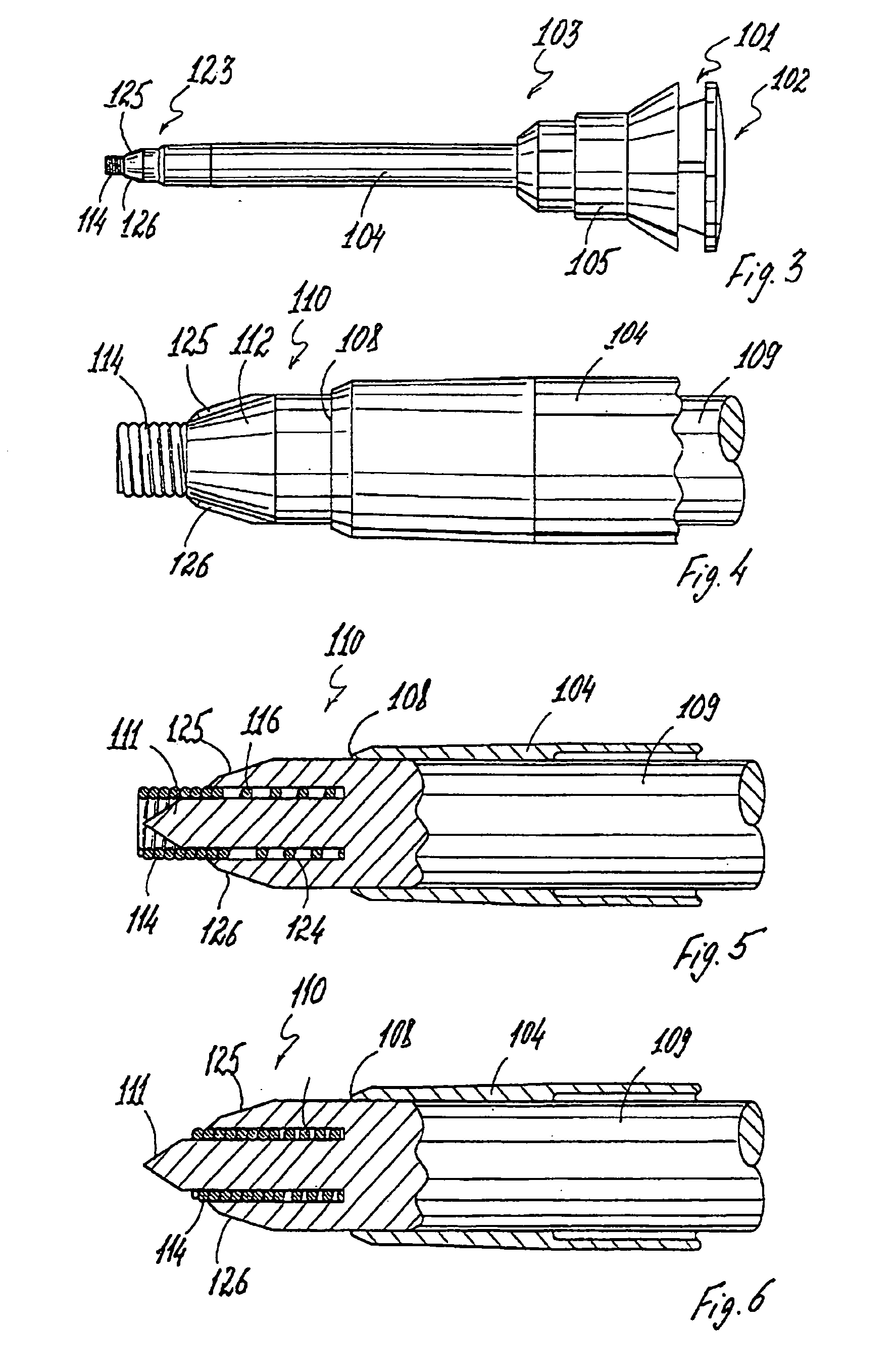
[0077] Before addressing specific implementations of the present invention in detail, it should be noted that the invention will be presented with reference to numerous examples, each of which illustrates one or more preferred feature of the invention. These various preferred features may each be used individually to advantage with an otherwise conventional trocar. In most preferred implementations, however, multiple preferred features are combined to provide a trocar with greatly enhanced levels of safety to the patient and / or professional staff, and / or to provide numerous other advantages as will become clear from the following description.

[0078] Turning now to the Figures, FIGS. 1 and 2 illustrate a first embodiment of a trocar assembly 1 in which a retractable shield 14 is deployed to selectively shield onl...


PUM


Abstract

A trocar assembly including a low-profile retractable shield deployable adjacent to a cutting element with a cross-sectional area which is small relative to the total cross-section of the assembly.

Description

CROSS-REFERENCE TO RELATED APPLICATIONS [0001] This application is a divisional application of U.S. patent application Ser. No. 09 / 936,741, filed Sep. 13, 2001, which was a U.S. National Phase Patent Application under 35 U.S.C. 371 of PCT International Application No. PCT / IB00 / 00408, which has an international filing date of Mar. 14, 2000, and which claims priority from Israel Patent Application No. 128,989, filed Mar. 15, 1999, all incorporated herein by reference in their entirety.FIELD OF THE INVENTION [0002] The present invention relates to medical equipment, in particular to trocar and similar devices used in surgical procedures and intended for their improvement. BACKGROUND OF THE PRIOR ART [0003] Trocars are used in medicine for making orifices and trocar port placement in body cavity walls used further for diagnostic or surgical instrument insertion into body cavity. Trocar insertion into body cavity can be accompanied with internal organ injury. To prevent such a complicati...

Claims


Application Information

Patent Timeline
Patent Type & Authority Applications(United States)
IPC IPC(8): A61B17/34
CPCA61B17/3417A61B17/3496A61B2017/3456A61B2017/346
Inventor POPOV
Owner POPOV
Why Eureka
Try Eureka