Expansion valve for refrigerating cycle

a technology of expansion valve and refrigerating cycle, which is applied in the direction of gas cycle refrigeration machines, refrigeration machines, lighting and heating apparatus, etc., can solve the problems of increasing cost, low theoretical cycle efficiency, and inability to determine the internal pressure of the temperature-sensing portion, so as to reduce and lessen the influence of temperature of the outside air

Inactive Publication Date: 2006-07-13
DENSO CORP
View PDF8 Cites 12 Cited by
  • Summary
  • Abstract
  • Description
  • Claims
  • Application Information

AI Technical Summary

Benefits of technology

[0029] With the expansion valve, the sum of a half of a volume of the first enclosed space and a volume of the second enclosed space can amount to 60% or more of the sum of a volume of the first enclosed space and the second enclosed space. Thereby, it is possible to lessen influences of temperature at a portion of the temperature-sensing portion except the temperature-sensing cylinder corresponding portion.
[0030] The expansion valve can further comprise a lid that cover

Problems solved by technology

However, the pressure control valve of the conventional type involves a problem that the weight is increased to lead to an increase in cost as there is a need for the casing 33 that covers the enclosed space (temperature-sensing portion).
Also, the case where CO2 is used as a refrigerant involves a problem that the theoretical cycle efficiency is lo

Method used


Image

  • Expansion valve for refrigerating cycle
  • Expansion valve for refrigerating cycle
  • Expansion valve for refrigerating cycle

Examples


first embodiment

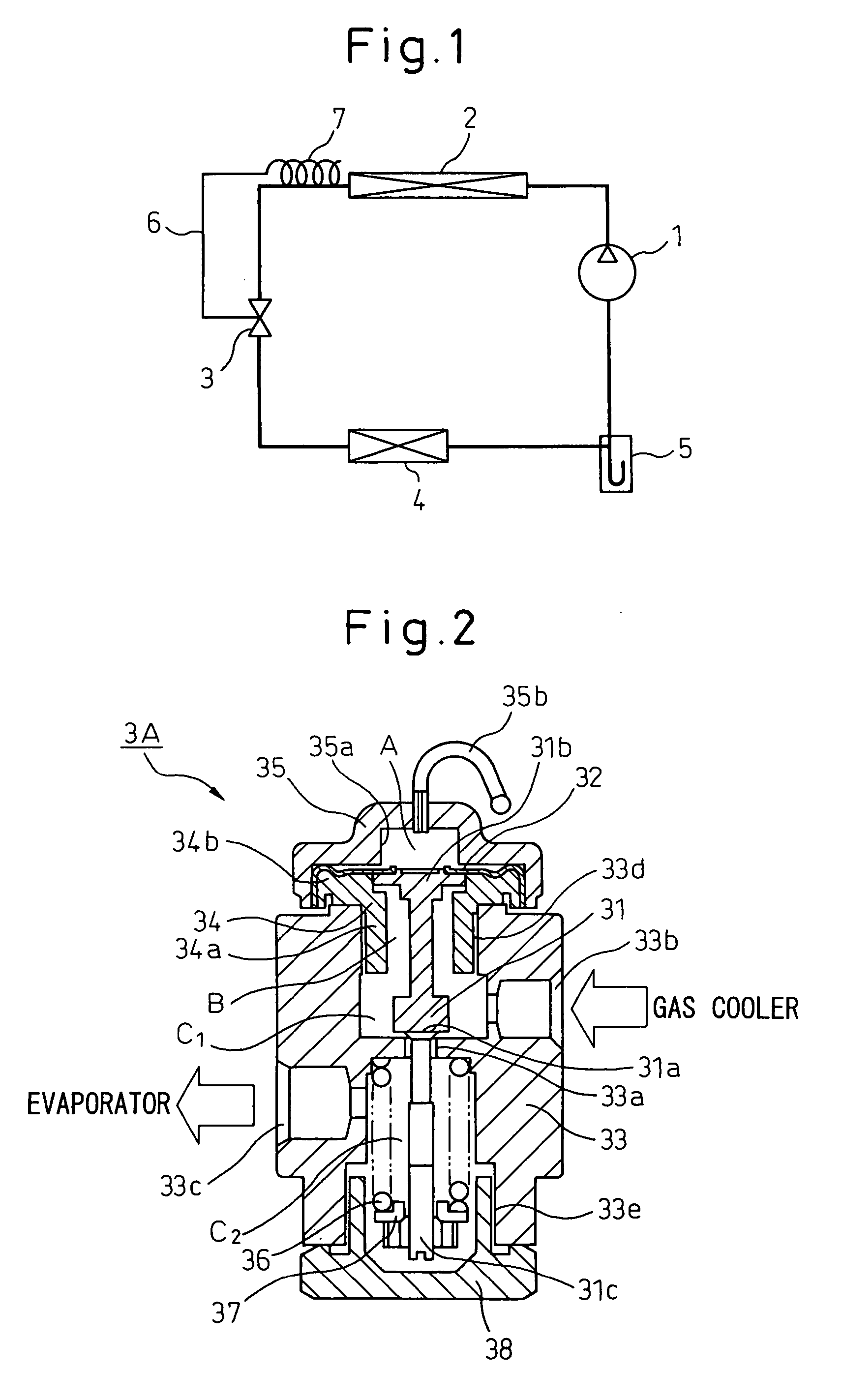
[0053] An expansion valve for a refrigerating cycle according to an embodiment of the invention will be described below with reference to the drawings. FIG. 1 is a view illustrating a vapor compression type refrigerating cycle (supercritical refrigerating cycle), in which CO2 is circulated as a refrigerant, and FIG. 2 is a cross sectional view showing an expansion valve for a refrigerating cycle, according to the invention, applied to the vapor compression type refrigerating cycle illustrated in FIG. 1. In FIG. 1, the reference numeral 1 denotes a compressor that sucks and compresses a refrigerant (CO2), and 2 a gas cooler (radiator) that cools the refrigerant compressed by the compressor 1. An expansion valve 3 is arranged on an outlet side of the gas cooler 2 to control a refrigerant pressure at the outlet side of the gas cooler 2 on the basis of a refrigerant temperature at the outlet side of the gas cooler 2, the expansion valve also functioning as a decompressor that decompress...

ninth embodiment

[0096] Typically, in the expansion valve 3I used in a refrigerating cycle provided with the internal heat exchanger illustrated with reference to FIG. 11, that density, at which a refrigerant is charged into the enclosed space A of the temperature-sensing portion of the expansion valve 3I, is set in the range of about 200 kg / m3 to about 600 kg / m3. In the case where a quantity of superheat is to be increased, an upper limit value of the range of charging density may be made in the order of about 570 kg / m3, and in the case where an elastic member for biasing in a valve closing direction is used in combination, the charging density can be made in the order of about 450 kg / m3. More desirably, that density, at which a refrigerant is charged into the temperature-sensing portion of the expansion valve, is set in the range of about 200 kg / m3 to about 450 kg / m3.

seventh embodiment

[0097] Further, for the expansion valve 3H used in a refrigerating cycle, in which the internal heat exchanger and illustrated with reference to FIG. 10 is used, the expansion valve being provided with no adjustment spring, it is preferable to adopt a charged refrigerant density being the same as that described above. That is, that density, at which a refrigerant is charged into the enclosed space A of the temperature-sensing portion of the expansion valve 3H and the cavity 31d, is set in the range of about 200 kg / m3 to about 600 kg / m3. In the case where a quantity of superheat is to be increased, an upper limit value in the range of charging density may be made in the order of about 570 kg / m3 and, further, in the case where an elastic member for biasing in a valve closing direction is used in combination, the charging density can be in the order of about 450 kg / m3. More desirably, that density, at which a refrigerant is charged into the temperature-sensing portion of the expansion...


PUM


Abstract

An expansion valve for a refrigerating cycle, in which the body dimensions and the weight of the whole valve can be reduced and a reduction in cost can be achieved.
An expansion valve of the invention comprising a temperature-sensing portion arranged in a refrigerant passage leading to an evaporator from a gas cooler or an internal heat exchanger in a vapor compression type refrigerating cycle and varied in internal pressure according to a refrigerant temperature at an outlet side of the gas cooler or on an outlet side of the internal heat exchanger, a valve member that mechanically interlocks with a change in internal pressure of the temperature-sensing portion to adjust an opening degree of a valve port, and a body that accommodates therein the valve member, and wherein the body is provided with a flow passage, through which a refrigerant reduced in pressure by the valve member is led to the evaporator while a refrigerant temperature at the outlet side of the gas cooler or on the outlet side of the internal heat exchanger is transmitted to the temperature-sensing portion. Also, that density, at which a refrigerant is charged in a temperature-sensing body, is set in the range of about 200 kg/m3 to about 600 kg/m3. Further, a ratio of a temperature-sensing cylinder corresponding portion to the temperature-sensing body is made at least 60%.

Description

BACKGROUND OF THE INVENTION [0001] 1. Field of the Invention [0002] The present invention relates to an expansion valve for a refrigerating cycle that controls a refrigerant on a radiator outlet side on the basis of a refrigerant temperature at the radiator (gas cooler) outlet side of a vapor-compression-type refrigerating cycle, and is especially suited to a supercritical refrigerating cycle that uses a refrigerant, such as carbon dioxide (CO2) or the like, in a supercritical range. [0003] 2. Description of Related Art [0004] Generally, it is known to use, as a vehicular air conditioning apparatus, a vapor-compression-type refrigerating cycle that circulates CO2 as a refrigerant in a closed circuit comprising a compressor 1, a gas cooler (radiator) 2, an expansion valve 3, an evaporator 4, an accumulator 5, etc. Conventionally, a pressure control valve as disclosed in JP-A-2000-193347 and JP-A-2003-254460 is known as a mechanical type expansion valve used in such a vapor compressio...

Claims


Application Information

Patent Timeline
IPC IPC(8): F25B41/04F25B41/00F25B41/06
CPCF25B41/062F25B2309/061F25B2341/063F25B2341/0683F25B41/335
Inventor MURASE, YOSHINORITOMATSU, YOSHITAKAKAKEHASHI, NOBUHARUOHTA, HIROMI
Owner DENSO CORP
Why Eureka
Try Eureka