Heat exchanger

a technology of heat exchangers and heat exchangers, applied in the field of heat exchangers, can solve the problems of reducing the reliability of such systems, adding cost and complexity to such systems,

Inactive Publication Date: 2006-07-13
VALENSA JEROEN +2
View PDF23 Cites 12 Cited by
  • Summary
  • Abstract
  • Description
  • Claims
  • Application Information

AI Technical Summary

Benefits of technology

[0007] It is another objective of the invention to provide a recuperative heat exchanger that is suitable for use in a fuel cell system.

Problems solved by technology

For example, the use of an active control system may add cost and complexity to such systems, while reducing the reliability of such systems.

Method used


Image

  • Heat exchanger
  • Heat exchanger
  • Heat exchanger

Examples


Embodiment Construction

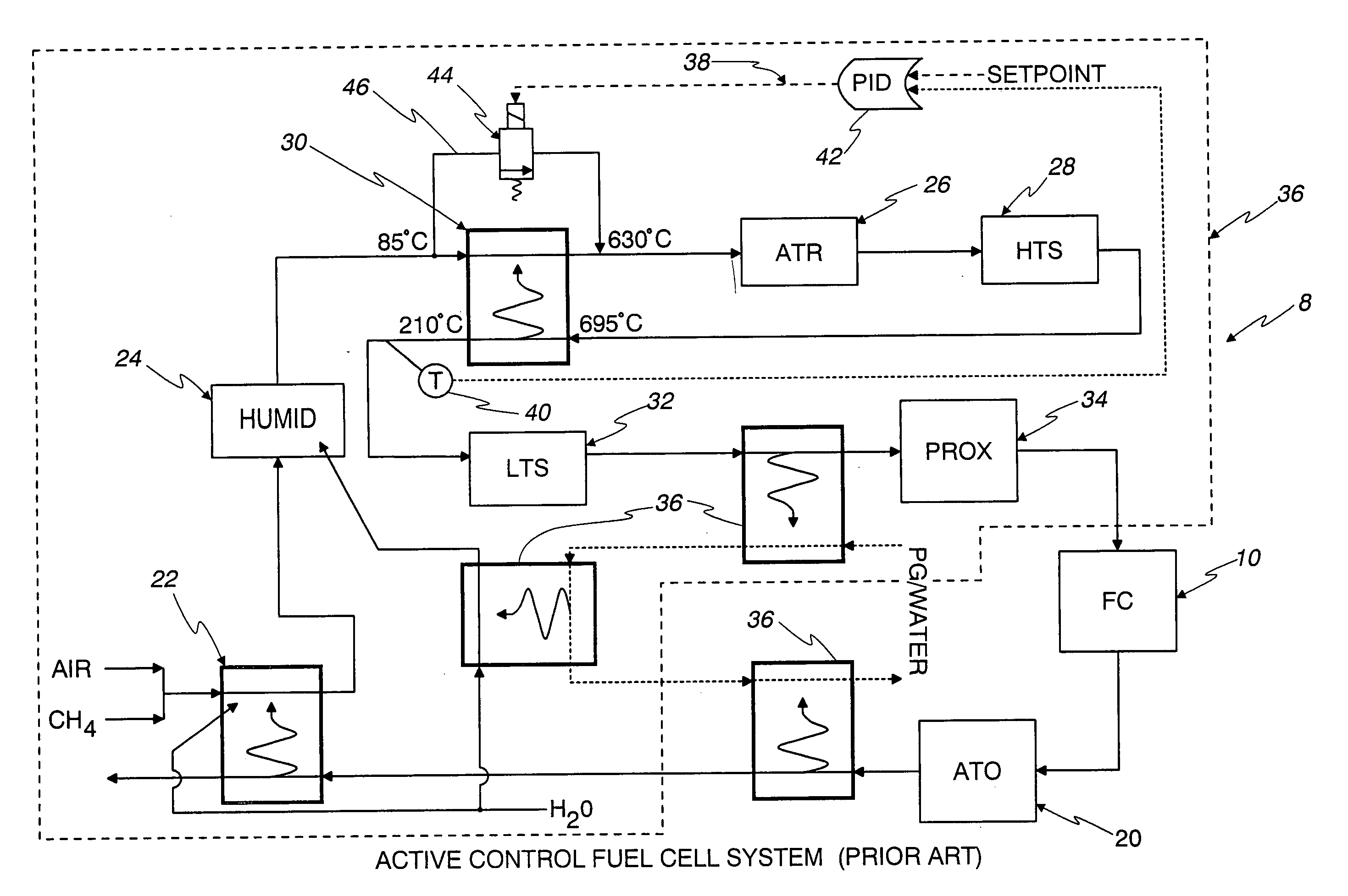
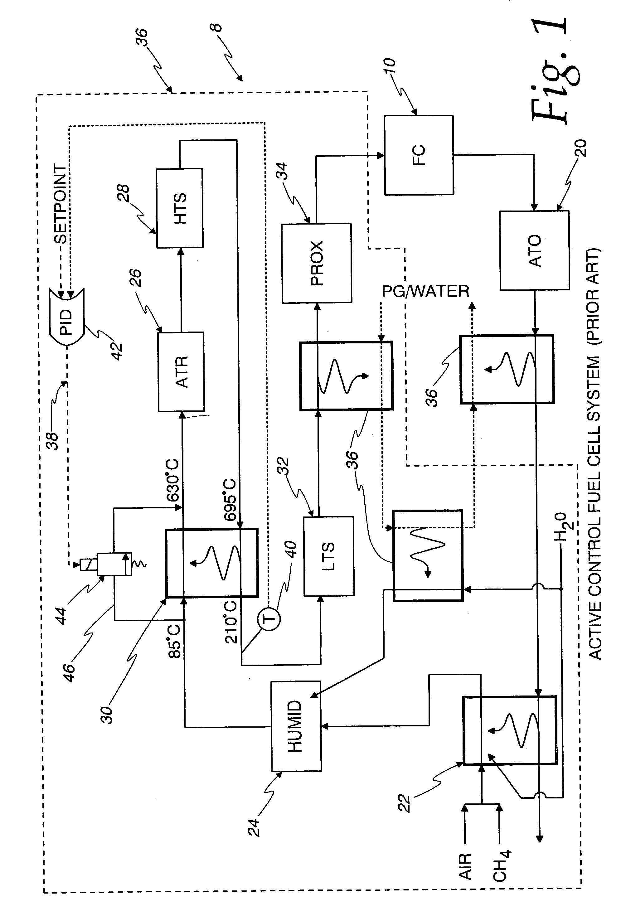
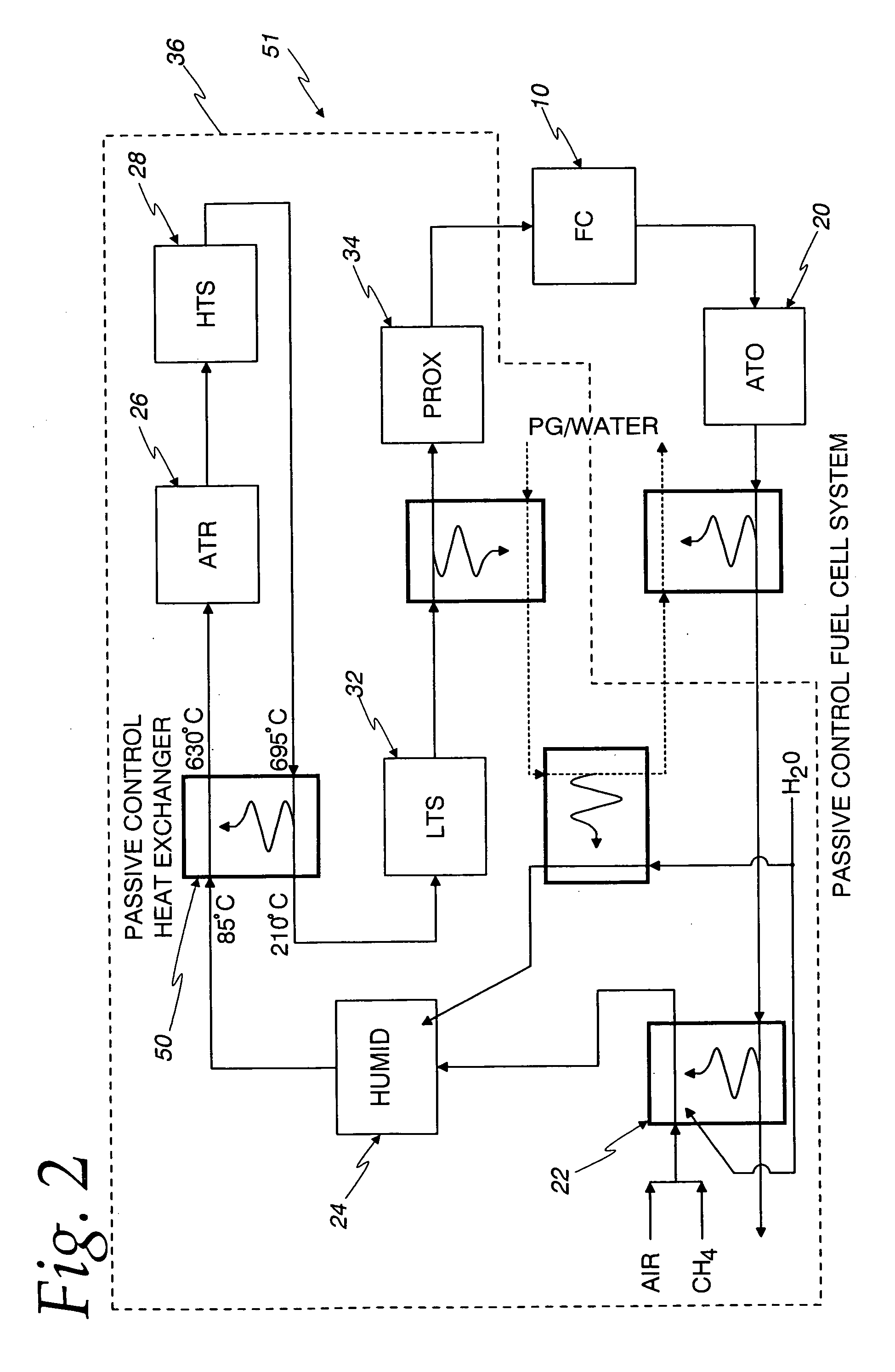
[0043]FIG. 2 shows a heat exchanger 50 embodying the present invention substituted for the recuperative heat exchanger 30 and its control system 38 shown in FIG. 1 in a proton exchange membrane type fuel cell system 51. With the exception of the substitution of the heat exchanger 50 for the heat exchanger 30 and it's control system 38, the fuel cell systems 8 and 51 shown in FIGS. 1 and 2, respectively, are identical and like reference numbers represent like components. While, the heat exchanger 50 made according to the invention is shown in FIG. 2 incorporated in the fuel processing system 36 of the proton exchange membrane type fuel cell system 51, it should be understood that heat exchangers according to the invention can and will find use in other applications. Accordingly, no limitation to use of the heat exchangers according to the invention with fuel cell systems or with particular types of fuel cell systems is intended, unless expressly recited in the claim. For example, whi...


PUM

PropertyMeasurementUnit
temperaturesaaaaaaaaaa

Abstract

A heat exchanger (50) is provided for transferring heat between first and second fluids (52) and (54) having a maximum operating mass flow rate through the heat exchanger (50) and mass flow rates that are substantially proportional to each other. The heat exchanger (50) provides essentially constant outlet temperatures for the first and second fluids (52,54) for all of the flow rates within the operating spectrum of the heat exchanger (50) without the use of an active control system. The heat exchanger (50) is of particular use in the fuel processing system (36) of proton exchange membrane type fuel cell systems.

Description

FIELD OF THE INVENTION [0001] This invention relates to heat exchangers in general and in more particular applications, to recuperative heat exchangers which find many uses in industry, including in fuel cell systems. BACKGROUND OF THE INVENTION [0002] Heat exchangers that transfer heat from one fluid flow to another fluid flow and wherein the mass flow rates of each of the fluid flows are substantially proportional to each other are known. Perhaps the most common example of such heat exchangers are recuperative heat exchangers that recoup or recover useful heat from the working fluid of a system as the working fluid flows through the system. One example of such a recuperative heat exchanger can be found in the fuel processing system of proton exchange membrane (PEM) type fuel cell systems. In typical fuel cell systems, a fuel, such as methane or a similar hydrocarbon, is used as the source of hydrogen for the fuel cell. This hydrocarbon must be reformed within the system prior to r...

Claims


Application Information

Patent Timeline
Patent Type & Authority Applications(United States)
IPC IPC(8): H01M8/06B01J19/00C01B3/38C01B3/48F28D7/16F28D9/00F28F9/22H01M8/02H01M8/04
CPCC01B3/382C01B3/48F28D7/1676F28D9/005F28D9/0075F28F9/22H01M8/04014H01M8/04074H01M8/0631Y02E60/50F28F2250/102Y02P20/129F28D9/00F28F3/00
Inventor VALENSA, JEROENREINKE, MICHAEL J.VOSS, MARK G.
Owner VALENSA JEROEN
Why Eureka
Try Eureka