Charged particle beam equipment and charged particle microscopy

a charge beam and equipment technology, applied in the direction of material analysis using wave/particle radiation, instruments, nuclear engineering, etc., can solve the problems of specimens that cannot be used for high magnification calibration, cannot be applied to the entire range of observation magnification of electron microscopes, and cannot be used for m calibration, etc., to reduce the effect of specimen dri

Active Publication Date: 2006-07-13
HITACHI HIGH-TECH CORP
View PDF6 Cites 25 Cited by
  • Summary
  • Abstract
  • Description
  • Claims
  • Application Information

AI Technical Summary

Benefits of technology

[0014] According to the present invention, by reducing effects of specimen drift, it becomes possible to calibrate a magnification error in other observation magnifications with a magnification error equal to that of a reference magnification. By using a dimensional standard specimen for calibrating the magnification of the reference magnification, it is possible to calibrate magnification errors at other observation magnifications for which a dimensional standard specimen cannot be used.

Problems solved by technology

For example, microscale specimens with a pitch interval of 0.24 μm cannot be used in the entire range of magnifications of a scanning electron microscope, above all, those specimens cannot be used for calibration of high magnifications.
Similarly, even when a lattice image of a gold single crystal thin-film specimen with a crystal lattice spacing of 0.204 nm is used as a dimensional standard, it cannot be applied to the entire range of observation magnifications of the electron microscope.

Method used


Image

  • Charged particle beam equipment and charged particle microscopy
  • Charged particle beam equipment and charged particle microscopy
  • Charged particle beam equipment and charged particle microscopy

Examples


Embodiment Construction

[0035] Description will be made of an embodiment of the present invention with reference to the accompanying drawings. The present invention is applicable to cases where the charged particle beam is an ion beam or an electron beam; however, the present invention will be described referring to a case where the charged particle beam is an electron beam in the following. In addition, the lens system, the beam deflector and the scanner may be either of the type using an electric field or of the type using a magnetic field; however, description will be made of a case where those devices of the magnetic field type are used. It does not matter at all whether there is a projection lens under a specimen or how many stage the projection lens may be.

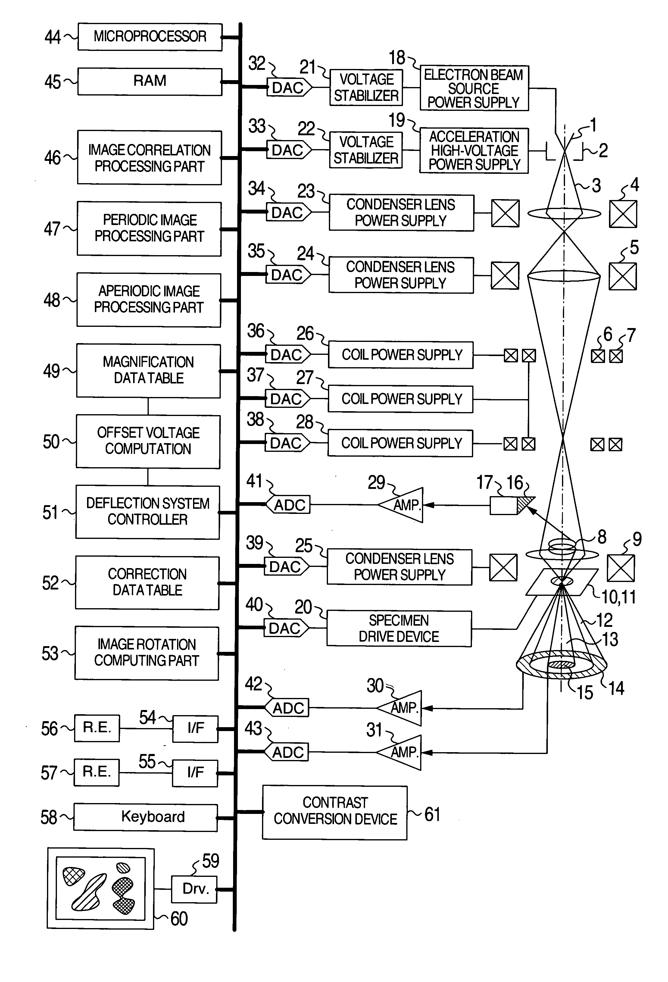
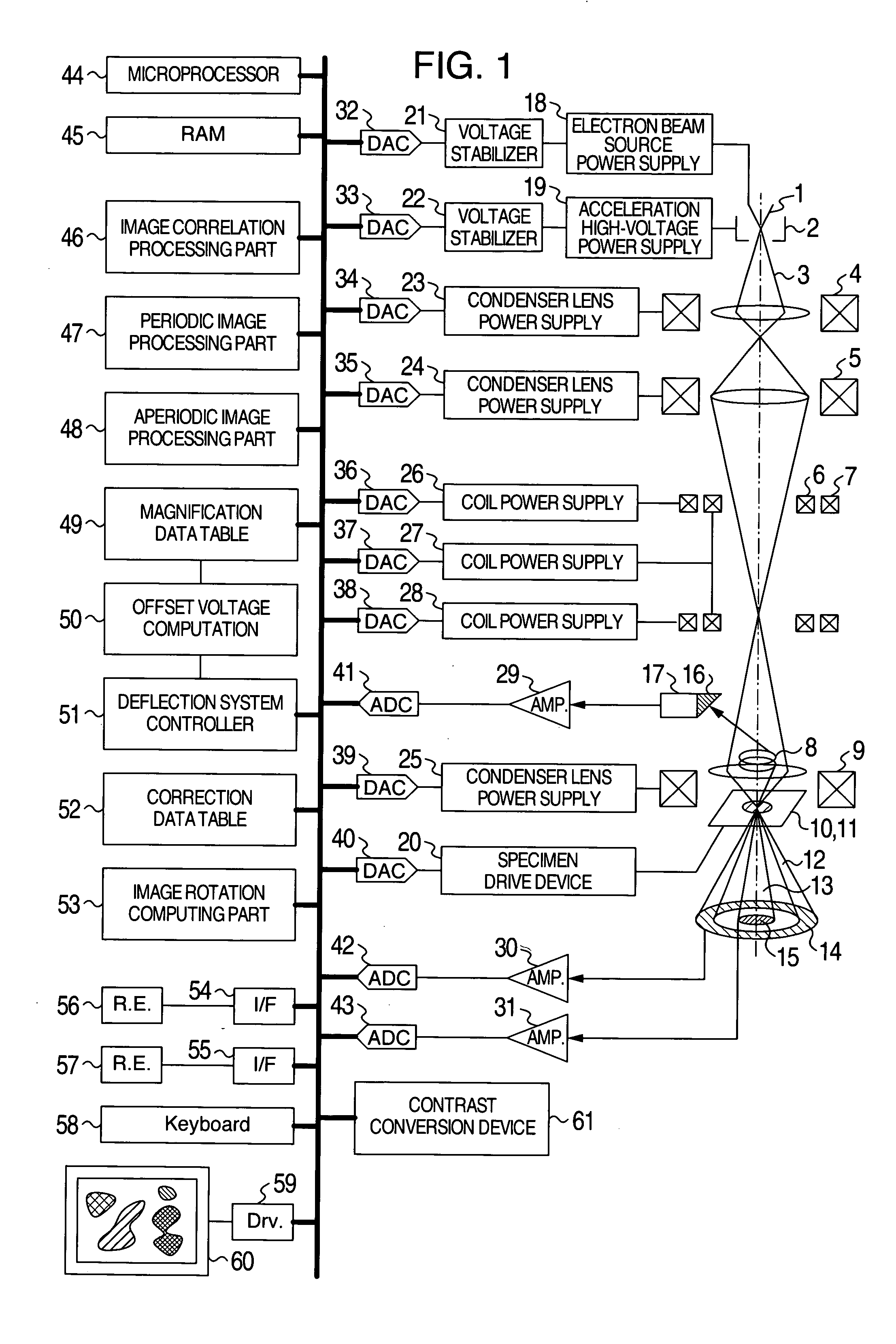
[0036]FIG. 1 is a schematic function block diagram as an example of charged particle beam equipment according to the present invention.

[0037] An electron beam (charged particle beam) 3 emitted from an electron beam source (charged particle beam s...


PUM


Abstract

On the basis of a displacement of the field of view before and after a deflection of a charged particle beam, extracted from a first specimen image, including a displacement of the field of view recorded by causing a charged particle beam to deflect by a predetermined amount by a beam deflector in an image in which a specimen image is captured at a first magnification calibrated by using a specimen enlarged image of a specimen as a magnification standard, and also a displacement of the field of view before and after a deflection of the charged particle beam, extracted from a second specimen image, including a displacement of the field of view recorded by causing a charged particle beam to deflect by the predetermined amount by the beam deflector in an image in which a specimen image is captured at a second magnification, the second magnification is calibrated.

Description

CROSS-REFERENCE TO RELATED APPLICATION [0001] The present invention is related (1) U.S. Pat. No. 6,791,084 and (2) U.S. patent application Ser. No. 11 / 038,478 entitled “CHARGED PARTICLE SYSTEM AND A METHOD FOR MEASURING IMAGE MAGNIFICATION” filed on Jan. 23, 2004. The disclosure of the above U.S. patent and application is herein incorporated by reference.BCKGROUND OF THE INVENTION [0002] 1. Field of the Invention [0003] The present invention relates to charged particle beam equipment for scanning a charged particle beam over a specimen, and forming an image by using a signal generated when the specimen is irradiated by a charged particle beam. [0004] 2. Description of the Related Art [0005] Heretofore, with charged particle beam equipment, such as a scanning electron microscope, a focused ion beam observation device, and a transmission electron microscope, when calibrating a magnification and a measured length of images accurately, is has been a usual practice to measure an interval...

Claims


Application Information

Patent Timeline
Patent Type & Authority Applications(United States)
IPC IPC(8): G21K7/00
CPCH01J37/222H01J37/265H01J37/28H01J2237/223H01J2237/2826H01J2237/3045
Inventor INADA, HIROMISATO, MITSUGUTAKANE, ATSUSHI
Owner HITACHI HIGH-TECH CORP
Why Eureka
Try Eureka