
Magnetic levitation of intraluminal microelectronic capsule

Inactive Publication Date: 2006-07-13
UTI LIMITED PARTNERSHIP
View PDF65 Cites 108 Cited by
  • Summary
  • Abstract
  • Description
  • Claims
  • Application Information

AI Technical Summary

Benefits of technology

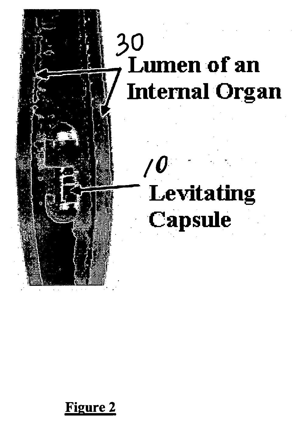
[0006] Diamagnetically-stabilized magnetic levitation is utilized as part of this invention to affix and / or steer autonomous devices, such as swallowed microelectronic capsules, in the lumens of internal organs. A set of external solenoids circumferentially arranged around a human body that contains the swallowed capsule can significantly ease the requirements for levitating and further controlling the said capsule by (1) moving the said solenoids, (2) moving the patient with respect to said solenoids, or (3) manipulating the electrical current through said solenoids in a controlled fashion, in order to steer and move the capsule in the internal organs of interest.
[0007] The capsule can provide the necessary feedback for its own location control by continuously reporting one or more of the following parameters: the pressure exerted upon it, its acceleration (which practically would reflect the extent of the impact of gravitational forces on the capsule), its velocity, and its position. Any or all of these feedback parameters of pressure, acceleration, velocity, and position can be used for assessing and controlling the location of the capsule and for assessing the gravitational and motility forces exerted upon it, so that necessary steering, movement, and stability control of the capsule by the external magnetic field can be accomplished. The capsule is affixed, i.e., held in position, by diamagnetic levitation, and steering is accomplished by changing the external magnetic field exerted on the levitating capsule. When a location of the capsule is determined to be not where it is desired to be, the magnetic field of the solenoid in relation to the capsule can be varied in a manner that steers and moves the capsule to such desired location and then affixed or held in that desired location.

Problems solved by technology

Some simple magnetic levitation techniques, however, require low temperatures and superconductors, which would not be practical for applications in intraluminal capsule endoscopy.

Method used


Image

  • Magnetic levitation of intraluminal microelectronic capsule
  • Magnetic levitation of intraluminal microelectronic capsule
  • Magnetic levitation of intraluminal microelectronic capsule

Examples


Embodiment Construction

[0019] The word “solenoid” is used here according to its general meaning of a long coil through which electric current flows, thereby establishing a magnetic field with a North and South poles on each end of the said solenoid. Levitation is the process by which an object is suspended against any force acting upon it (in the case considered here, namely gravity or peristalsis), in a stable position by a force without physical contact. Changing the position of the applied force causing the levitation can bring about the controlled movement of the levitating body.

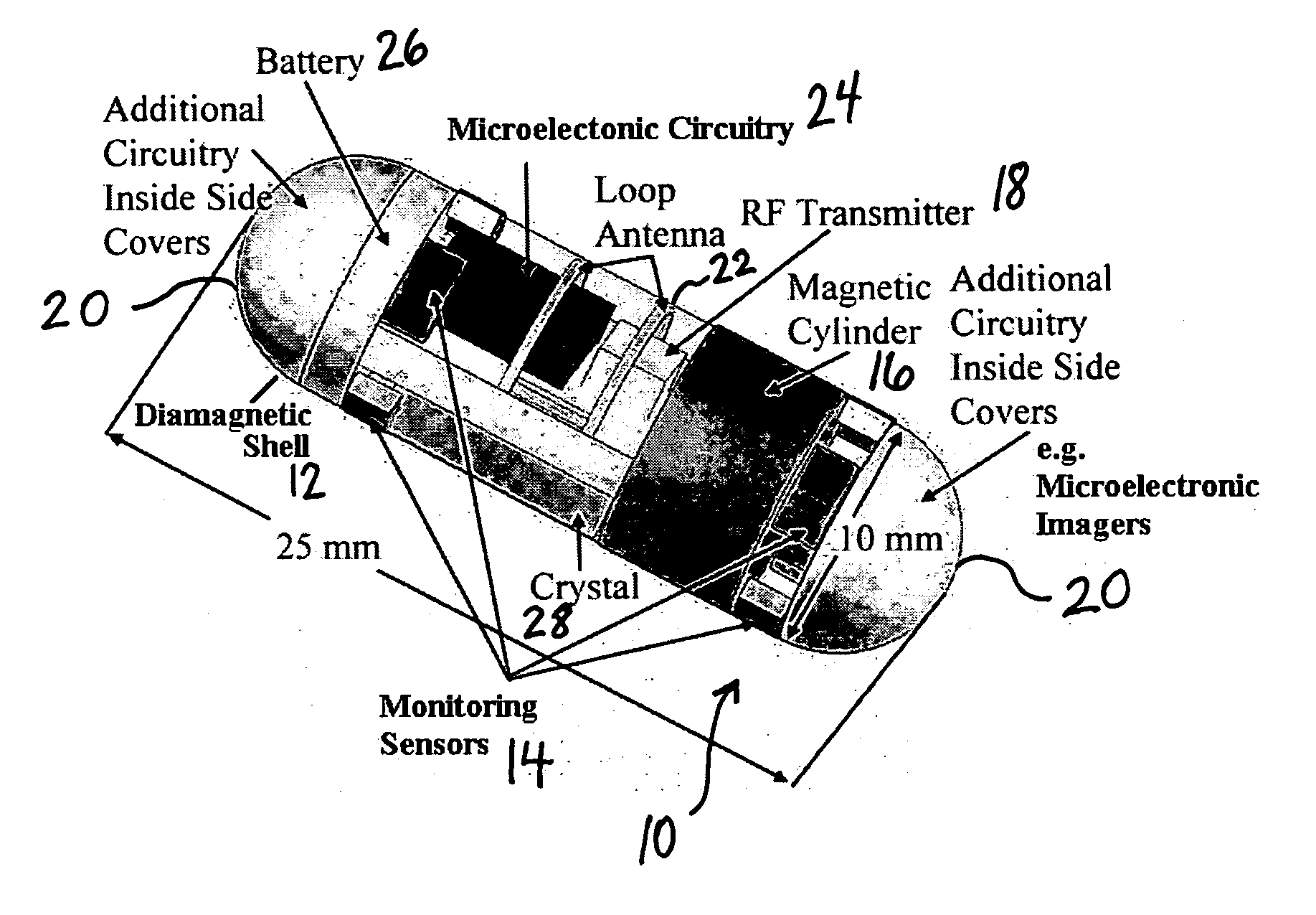
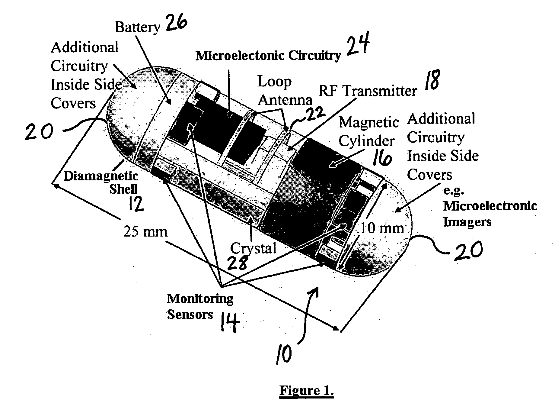
[0020] Referring to FIG. 1 a diamagnetically levitatable intraluminal microelectronic capsule 10 is shown that is comprised of a shell 12 of the capsule, which may or may not contain a cylinder of appropriate diamagnetic material (e.g. bismuth, antimony, pyrolytic graphite, carbon graphite, gold, etc.), microelectronic components or sensors 14 related to the testing or monitoring function of the capsule in the body, for examp...


PUM


Abstract

A method and apparatus for magnetically levitating and further steering of an intraluminal device, such as a swallowable microelectronic capsule, for monitoring bodily functions is provided. The method comprises diamagnetically-stabilized levitation, followed by dynamic modification of the external magnetic field producing the said levitation, so that the levitating intraluminal device can be steered in desired direction. The said intraluminal device contains appropriate sensors and reports in real time the forces and pressures exerted on it, as well as its position, so that the levitation and the steering can be dynamically adjusted using appropriate dynamic control of external magnetic devices such as solenoids.

Description

CROSS-REFERENCE TO RELATED APPLICATIONS [0001] This application claims the benefit under 35 USC 119(e) of U.S. provisional patent applications 60 / 643,392 filed Jan. 11, 2005 and 60 / 719,887 filed Sep. 23, 2005, the content of each of which is hereby incorporated by reference.FIELD OF INVENTION [0002] The present invention is related to apparatus and methods for intraluminal inspection of internal organs of a human or animal body, and more specifically to affixing or positioning and further controlling or steering autonomous microelectronic capsules equipped with one or more sensors for monitoring postion of the capsule in lumens of internal organs and with one or more sensors for sensing one or more physiological condition(s) in the internal organs and with means for communicating such position and physiological information or data to receiver means outside the body. BACKGROUND OF INVENTION [0003] The possibility for using smart pills or miniature microelectronic capsules which have ...

Claims


Application Information

Patent Timeline
IPC IPC(8): H01H1/08
CPCA61B1/00016A61B1/00036A61B1/00158A61B1/041A61B5/037H02N15/00A61B5/065A61B5/073A61B5/14539A61B5/42A61B2562/0219A61B5/062
Inventor MINTCHEV, MARTIN P.WU, BILLY T.
Owner UTI LIMITED PARTNERSHIP
Learn More