
Multispectral imaging system comprising new multispectral optics

Active Publication Date: 2016-03-10
THE UNITED STATES OF AMERICA AS REPRESENTED BY THE SECRETARY OF THE NAVY
View PDF10 Cites 0 Cited by
  • Summary
  • Abstract
  • Description
  • Claims
  • Application Information

AI Technical Summary

Benefits of technology

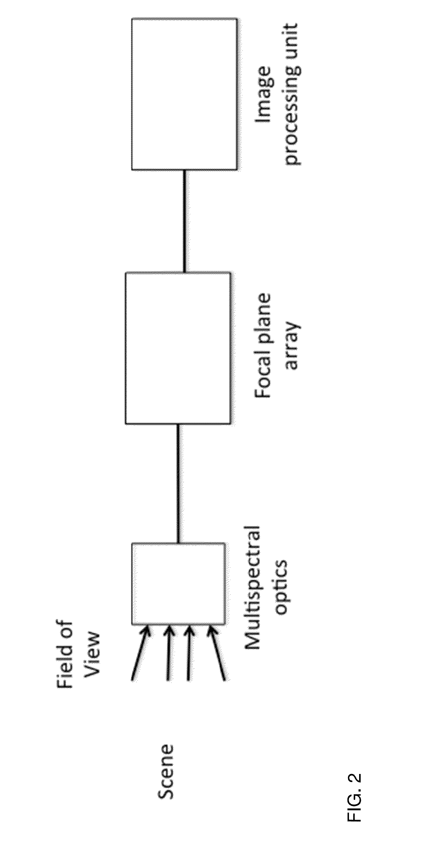
The present invention is a compact, multispectral imaging system that uses a set of refractive optical elements to focus light from different spectral bands to a common focal plane. This system is smaller and lighter than previous designs, as it uses new optical materials or combines existing materials to better meet the requirements of infrared imaging. The new materials have low do / dT, making them easier to athermalize the imaging system. The glass map of the system is similar, which simplifies co-molding and reduces costs. The design of the system is flexible and can be improved by using the best combinations of materials. Overall, the invention offers better performance and functionality in a smaller and lighter package than existing solutions.

Problems solved by technology

The visible imagers operate between the wavelengths (λ) of about 0.4 μm to 0.7 μm and provide very high-resolution imagery in clear daylight; however, the imagery is very limited on a hazy day with significantly reduced resolution and range.
Often, imaging in a single band is not enough for positive target identification for the reasons described above.
However, these imagers are typically bulky and have a very narrow field of view.
Applications such as wide area surveillance require very wide field of view that can only be achieved through refractive optics.
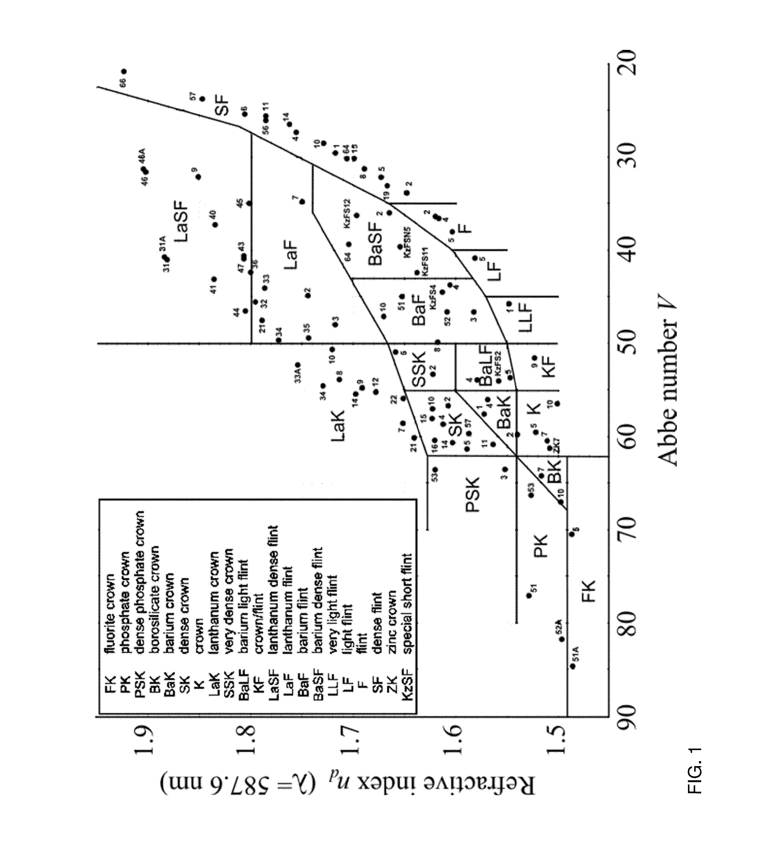
Currently there are very few optical materials commercially available that cover the transmission range from SWIR to LWIR.
Such an imager will be very heavy and it will be challenging to meet tolerances due to the alignment of all eleven elements and optical distortion in a useful temperature range of −50° C. to 50° C. due to the difference in the thermo-optic coefficient (dn / dT) of the individual elements.
The limited number of optical materials to choose from leads to complex lens systems with either poor imaging performance or excessive size and weight due to the use of a large number of optical elements needed to meet the specifications of required image quality.
Use of a large number of optical elements also makes the alignment tolerances very challenging.
Another drawback of using an imaging system with a large number of optical elements is the large number of air-optic interfaces resulting in Fresnel reflection loss per surface (R) given by the relation:
These Fresnel reflection losses multiply with increasing number of air / optic interfaces from the increased number of optical elements and reduce the overall brightness of the image.
Diffraction fundamentally limits the maximum attainable MTF of an imaging system.
Imagers with resolutions as good as this theoretical limit are not uncommon and are said to be diffraction limited.
One challenge in designing and building a multispectral imager with reduced size, weight and improved performance, is reducing the weight of the imaging optics, since the focal plane array (FPA) sensors are becoming more capable and more compact.
However, the choice becomes very limited for MWIR and LWIR with only a handful of optical materials.
The harder the lens designs are pushed due to smaller pixels, larger FPA sizes, broader spectral bands, the more limited one becomes by the traditional materials and optics.

Method used


Image

  • Multispectral imaging system comprising new multispectral optics
  • Multispectral imaging system comprising new multispectral optics
  • Multispectral imaging system comprising new multispectral optics

Examples


example 1

Cooled IR Dual-Band (MWIR-LWIR) Imaging Lens Design

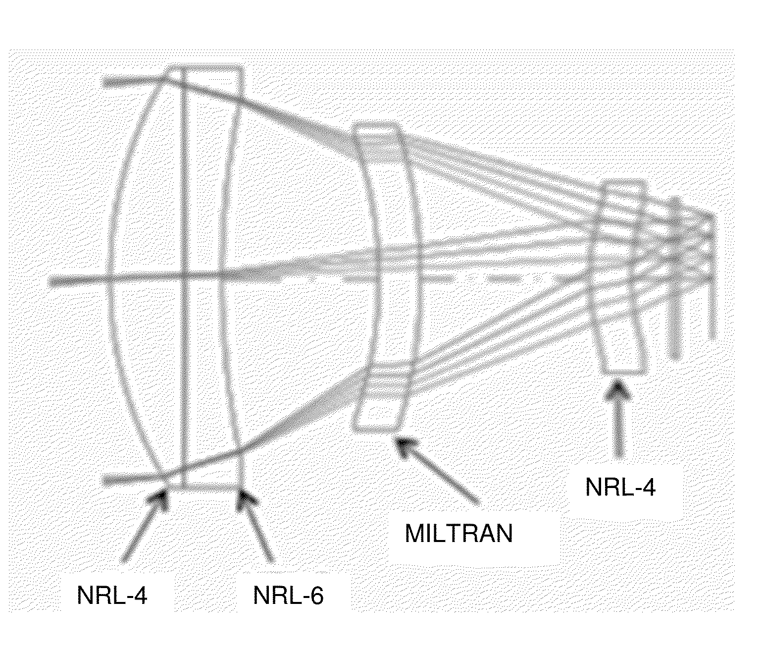
[0047]A generic cooled IR design is demonstrated utilizing both a traditional all-crystal design (FIG. 6) and comparing it to a design utilizing the materials of the present invention (FIG. 7). Both of these designs and the design in FIG. 8 utilize the same set of parameters described in Table 3. These relatively simple fixed focal length designs provide a useful comparison of the capabilities of the materials of the present invention. In this case, the MWIR spectrum is chosen to be 3.5-5.0 μm and the LWIR is 8.0-10.0 μm. These values are based on traditional spectral bands for cooled IR systems. All of the designs are also for a common focal length, f / number, and cold shield height of 1.0″. The designs are evaluated as if they are being used with a 12 μm pixel pitch detector.

TABLE 3First order imager specifications for thethree cooled IR dual-band designs.1st Order Optical PropertiesFocal Length66mmF / number2.5EPD (Entrance Pupil Di...

example 2

Uncooled IR Dual-Band (MWIR-LWIR) Imaging Lens Design

[0052]One way to further demonstrate the benefit of expanding the glass map is by designing an imaging system to more challenging performance. In this case, the design was focused on a dual band uncooled lens concept. This results in two changes that complicate the design, and one that simplifies it. The complication lies in going to a faster f / number and a broader spectral band. The faster f / number requires greater power from the lenses, which in general makes it harder to perform the required color correction. The broader spectral band is a result of the broadband nature of an uncooled FPA where the LWIR radiation can generally be observed out to 14 μm. The MWIR spectral band is assumed to be held the same, but the challenge of imaging the extra 4 μm (from 10.0-14.0 μm), is significant as it impacts the selection of materials and their choice for color correction. The lens is simplified by now allowing the aperture stop (no long...


PUM


Abstract

A compact multispectral imaging system comprising a set of optical elements capable of simultaneously focusing light from one or more spectral bands (SWIR, MWIR, and LWIR) to a common focal plane and a detector capable of capturing the multispectral image, wherein the optical elements comprise optics made from new optical materials or in combination with existing optical materials that transmit in multispectral wavelength regions.

Description

PRIORITY CLAIM[0001]The present application is a non-provisional application claiming the benefit of U.S. Provisional Application No. 62 / 047,725, filed on Sep. 9, 2014 by Shyam S. Bayya et al., entitled “Multispectral Imaging System Comprising New Multispectral Optics,” the entire contents of which is incorporated herein by reference.BACKGROUND[0002]1. Field of the Invention[0003]The present invention relates to multispectral imaging using optical elements capable of simultaneously focusing light from one or more spectral bands to a common focal plane and a detector capable of capturing the multispectral image.[0004]2. Description of the Prior Art[0005]Imaging in several spectral bands is used for surveillance and reconnaissance. Some of the examples include imaging in day and night by soldiers for situational awareness on a battlefield, aerial reconnaissance or surveillance over land for border protection, at sea for platform protection, or for property protection. Each spectral ba...

Claims


Application Information

Patent Timeline
IPC IPC(8): G01J3/28
CPCG01J2003/2826G01J3/2823G01J3/0208G02B7/028G02B1/02G02B13/146
Inventor BAYYA, SHYAM S.GIBSON, DANIEL J.NGUYEN, VINH Q.SANGHERA, JASBINDER S.VIZGAITIS, JAY
Owner THE UNITED STATES OF AMERICA AS REPRESENTED BY THE SECRETARY OF THE NAVY
Learn More