State validation using bi-directional wireless link

a wireless link and state validation technology, applied in the field of building monitoring and control, can solve the problems of power requirement partially negating the wireless advantage of radio frequency units, high cost of installing hard-wired systems in existing buildings, and inability to accurately detect the status of the state, so as to reduce false alarms

Inactive Publication Date: 2006-07-13
HONEYWELL INT INC
View PDF66 Cites 30 Cited by
  • Summary
  • Abstract
  • Description
  • Claims
  • Application Information

AI Technical Summary

Benefits of technology

[0011] The present invention includes a building monitoring and / or control system that includes bi-directional radio frequency links between master and remote units wherein the remote units preferably operate in a low power, non-transceiving state a majority of the time. The system can include at least one master unit and a plurality of remote units, the remote units being typically coupled to sensors for measuring and / or controlling security or building environment variables. The remote units in most systems can operate in a low power consumption state in which the unit can neither transmit nor receive, in a receive state in which the unit consumes more power and can receive transmissions from the master unit, and in a transmit state in which the unit consumes more power and can transmit messages to the master unit. Some embodiments include armed states in which the remote unit can sense and transmit data, and disarmed states in which the remote unit cannot, in combination, sense and transmit data. Disarmed states can provide a low power consumption state in which power is consumed neither for sensing variables nor for transmitting data.
[0016] In some systems, the master unit, upon receiving an event from a remote unit, can request a re-read of the sensor to validate the event before taking further action. A decision whether to request a re-read can be based on the sensor type and the current mode of the system. In one embodiment, the sensor type is transmitted along with the data. The sensor type is determined in another embodiment by the master looking up the remote unit ID and determining the sensor type or types associated with it. The sensor type is determined in another embodiment by the master looking up the sensor type in a previously built table. The table can be built from data obtained at initialization of either the remote units or the master unit. The information associated with a remote unit sensor can include whether to re-read, how long to wait before a re-read, and how many times to re-read. The validation functionality can greatly reduce false alarms.

Problems solved by technology

Installing hard-wired systems can be very expensive in existing buildings due in part to the labor costs of snaking wires through existing walls and ceilings.
In particular, on a point-by-point basis, retrofitting residential dwellings can be expensive because houses are often not designed to be continually changed, as are many office buildings.
The power requirement can partially negate the wireless advantage of radio frequency units, as some wiring is still required.
Remote units often transmit sensor data for needlessly long periods, and at higher power than is required, as there is no bi-directional capability, and therefore no way for the master unit to acknowledge receipt of the first remote unit message, or a low power message.
The periodic transmissions can be scheduled at the remote units by DIP switches or local programming of the remote units, but typically cannot be adjusted by the master unit as the communication between master and remote is unidirectional and the master has no way to adjust the timing of transmissions of the remote units.
Since there is no coordination between the transmission times of the remote units, collisions can occur between remote unit transmissions, which may reduce the overall reliability of the system.
To increase the probability that a particular remote unit transmission is received by the master, the remote unit may make the same transmission many times. However, this can significantly increase the power consumed by the remote units.
Another limitation is that false alarms can be generated.
False alarms undermine the credibility of real alarms and can cost money to respond to.
Many municipalities charge large fees for false alarms that are reported to police departments.
Too many false alarms can result in all or part of a security system to be ignored or turned off entirely.
For HVAC systems, false alarms can cause, for example, heat to be applied even if it is not desired.
As can be seen, this can decrease the efficiency of the HVAC system.

Method used


Image

  • State validation using bi-directional wireless link
  • State validation using bi-directional wireless link
  • State validation using bi-directional wireless link

Examples


Embodiment Construction

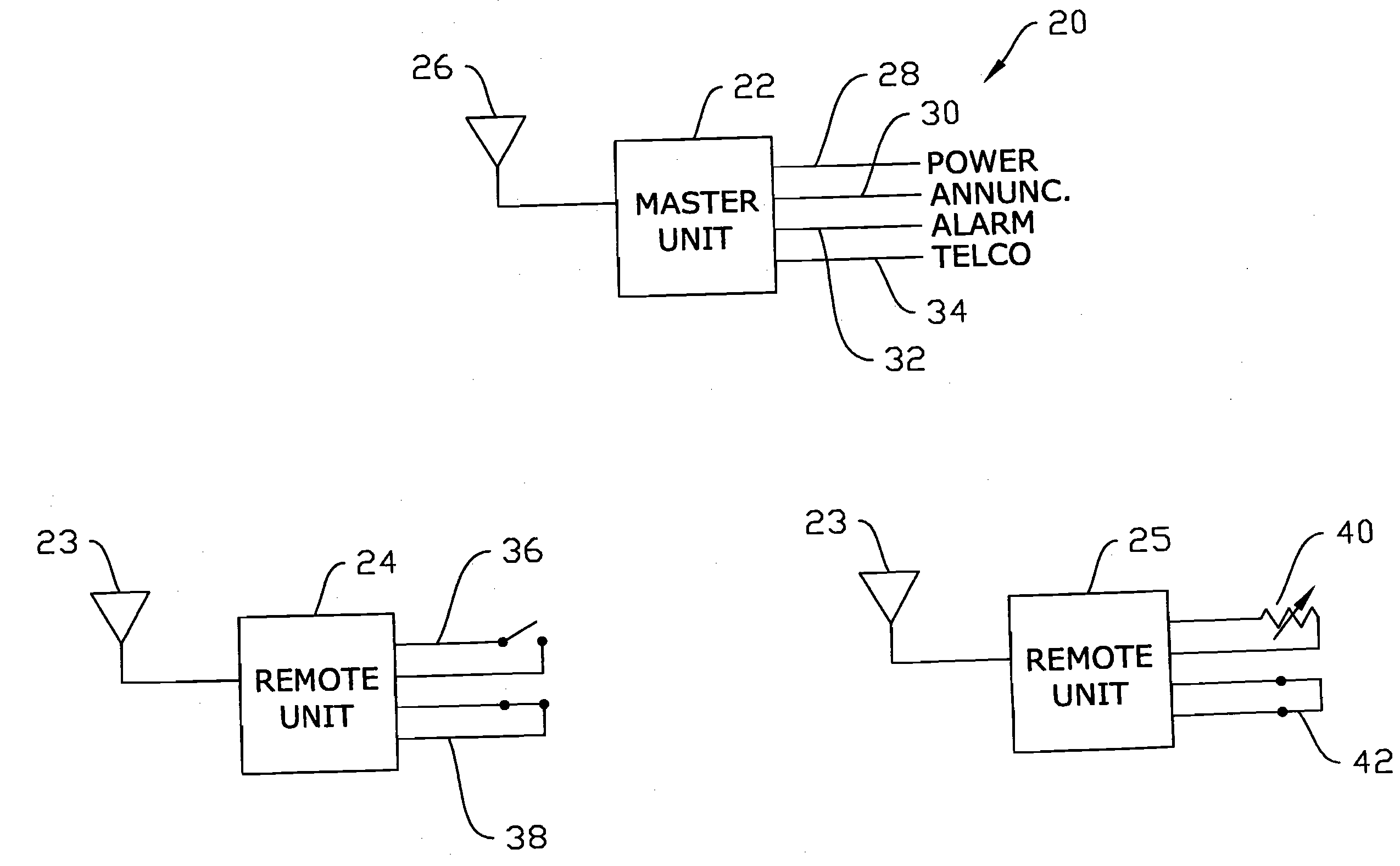
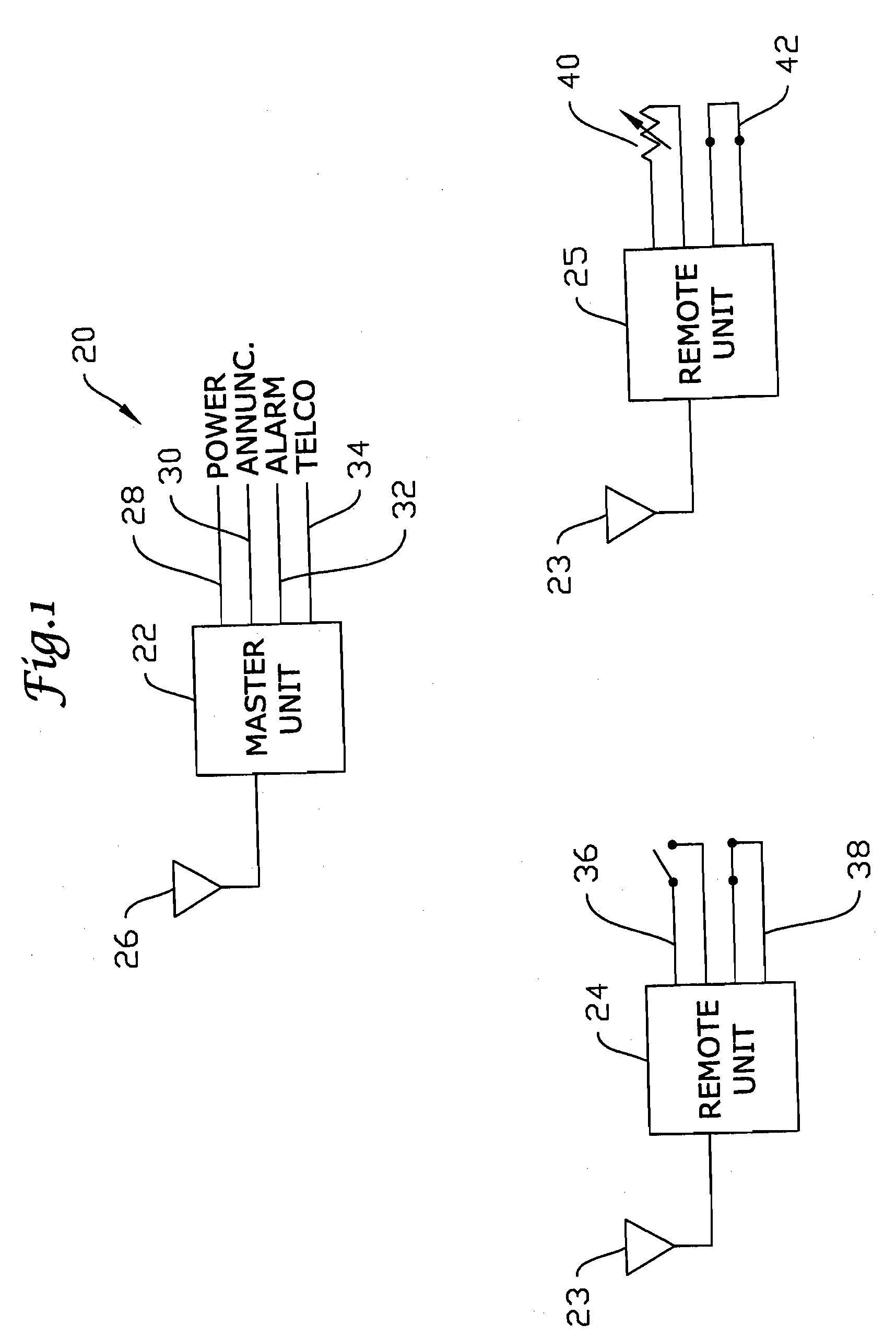
[0023]FIG. 1 illustrates a wireless control system 20 including a master unit 22 and two wireless remote units 24 and 25. Master unit 22 includes an antenna 26, a power supply line 28, annunciator panel output line 30, alarm device output line 32, and telephone line 34. A building monitoring and / or control system according to the present invention typically has at least one master unit which is commonly powered with AC line power but can be battery powered, or have battery back-up power. Remote unit 24 includes an antenna 23 and is coupled to two discrete sensor inputs 36 and 38. Sensor input 36 is a normally open sensor and sensor input 38 is a normally closed sensor. Sensors 36 and 38 can be reed switches or Hall effect devices coupled to magnets used to sense door and window opening and closing. Sensor 38 can be a foil continuity sensor used to detect glass breakage. Remote unit 25 includes antenna 23 and two analog sensors 40 and 42. Sensor 40 is a variable resistance device and...


PUM


Abstract

Building monitoring and control systems including bi-directional radio frequency links between master and remote units wherein the remote units operate in a low power, non-receiving state a majority of the time is disclosed. The bi-directional capability allows coordinated scheduling which aids in allowing the remote units to transmit data only at periodic time intervals to extend battery life. The bi-directional capabilities also allow for re-read requests for alarm validation and for putting remote units in armed and disarmed states for power conservation.

Description

[0001] This application is a continuation of U.S. application Ser. No. 09 / 311,092 filed May 13, 1999. CROSS REFERENCE TO CO-PENDING APPLICATIONS [0002] The present application is related to U.S. patent application Ser. No. ______ filed ______, entitled “Output Buffer With Independently Controllable Current Mirror Legs”; U.S. patent application Ser. No, ______, filed ______, entitled “Differential Filter with Gyrator”; U.S. patent application Ser. No. ______, filed ______, entitled “Compensation Mechanism For Compensating Bias Levels Of An Operation Circuit In Response To Supply Voltage Changes”; U.S. patent application Ser. No. ______, filed ______, entitled “Filter With Controlled Offsets For Active Filter Selectivity and DC Offset Control”; U.S. patent application Ser. No. ______, filed ______, entitled “Wireless System With Variable Learned-In Transmit Power”; and U.S. patent application Ser. No. ______, filed _____, entitled “Wireless Control Network With Scheduled Time Slots”, ...

Claims


Application Information

Patent Timeline
Patent Type & Authority Applications(United States)
IPC IPC(8): G05B23/02G08B26/00G08B25/04H04Q9/00
CPCG08B26/007
Inventor HELGESON, MICHAEL A.
Owner HONEYWELL INT INC
Why Eureka
Try Eureka