

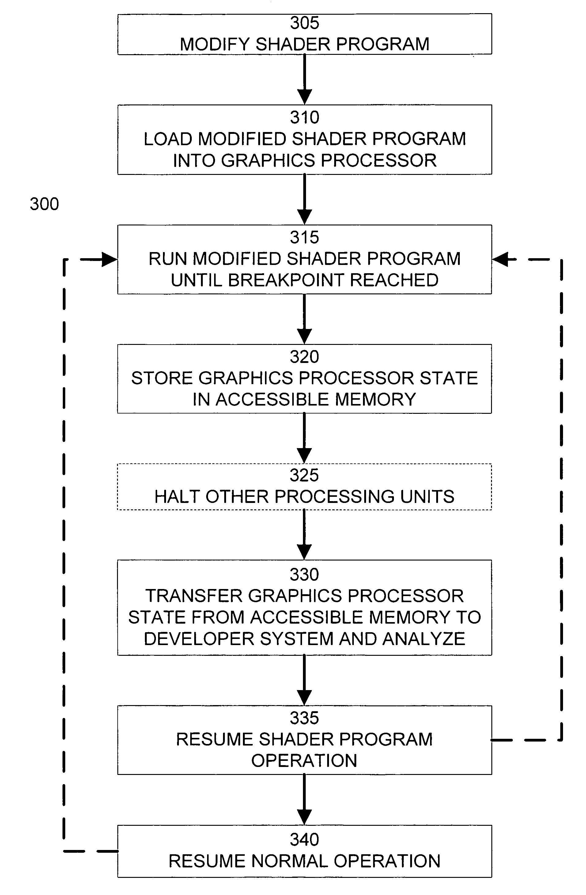
Interactive debugging and monitoring of shader programs executing on a graphics processor
a graphics processor and shader technology, applied in the field of computer graphics, can solve the problems of increasing size and complexity, increasing the difficulty of tuning the performance of shaders, and increasing the difficulty of eliminating errors,
- Summary
- Abstract
- Description
- Claims
- Application Information
AI Technical Summary
Problems solved by technology
Method used
Image

Examples
Embodiment Construction
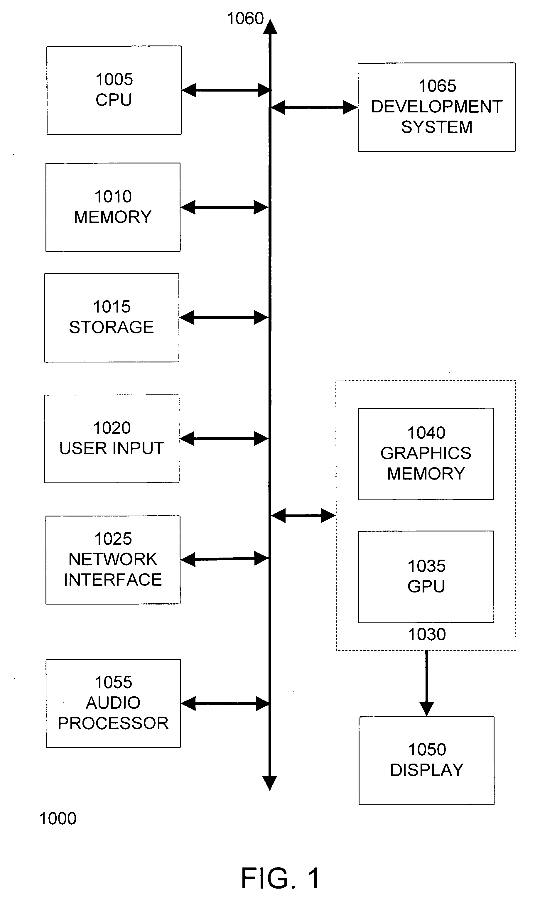
[0025]FIG. 1 is a block diagram of a computer system 1000, such as a personal computer, video game console, personal digital assistant, or other digital device, suitable for practicing an embodiment of the invention. Computer system 1000 includes a central processing unit (CPU) 1005 for running software applications and optionally an operating system. CPU 1005 may be comprised of one or more processing cores. Memory 1010 stores applications and data for use by the CPU 1005. Storage 1015 provides non-volatile storage for applications and data and may include fixed disk drives, removable disk drives, flash memory devices, and CD-ROM, DVD-ROM, Blu-ray, HD-DVD, or other optical storage devices. User input devices 1020 communicate user inputs from one or more users to the computer system 1000, examples of which may include keyboards, mice, joysticks, touch pads, touch screens, still or video cameras, and / or microphones. Network interface 1025 allows computer system 1000 to communicate wi...
PUM
 Abstract
Description
Claims
Application Information