Micro-oscillating member, light-deflector, and image-forming apparatus
a micro-oscillating member and light-deflector technology, applied in piezoelectric/electrostrictive/magnetostrictive devices, instruments, optics, etc., can solve the problem of not constant angular velocity, the type of light defector is unable to fully obtain the maximum usable defection angl
- Summary
- Abstract
- Description
- Claims
- Application Information
AI Technical Summary
Benefits of technology
Problems solved by technology
Method used
Image
Examples
first embodiment
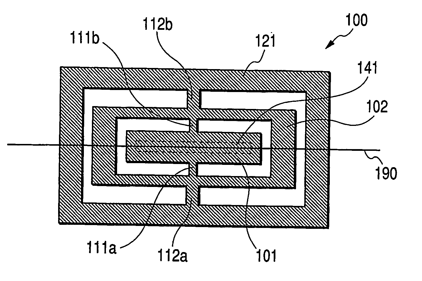
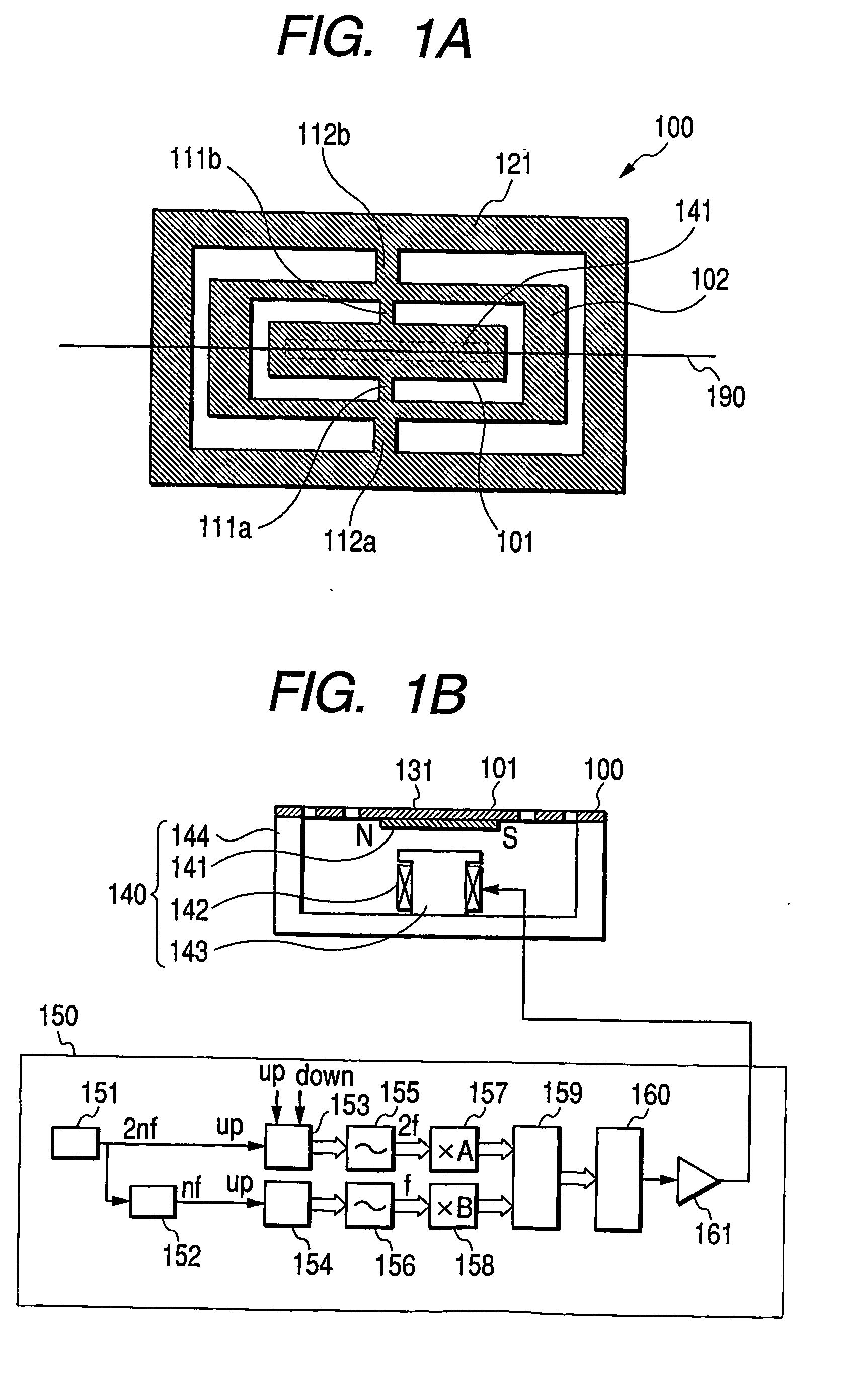
[0073]FIGS. 1A and 1B are views for explaining a light-deflector of the present embodiment. The light-deflector of the present embodiment consists of the micro-oscillating member and a light-reflecting film 131 formed on the upper surface of a movable element 101. And the micro-oscillating member consists of a plate member 100, a electromagnetic actuator 140 and a controller 150.
[0074]FIG. 1A is a top view of a plate member 100 formed by etching-forming a silicon wafer. A flat movable element 101 is supported up and down in FIG. 1A by two pieces of torsion springs 111a and 111b. A frame-shaped movable element 102 supports the torsion springs 111a and 111b in its interior side, and is supported above and below in FIG. 1A by two pieces of torsion springs 112a and 112b. A frame-shaped support frame 121 supports the torsion springs 112a and 112b in its interior side. While the movable elements 101 and 102 and the torsion springs 111 and 112 have two oscillation modes, their frequencies...
second embodiment
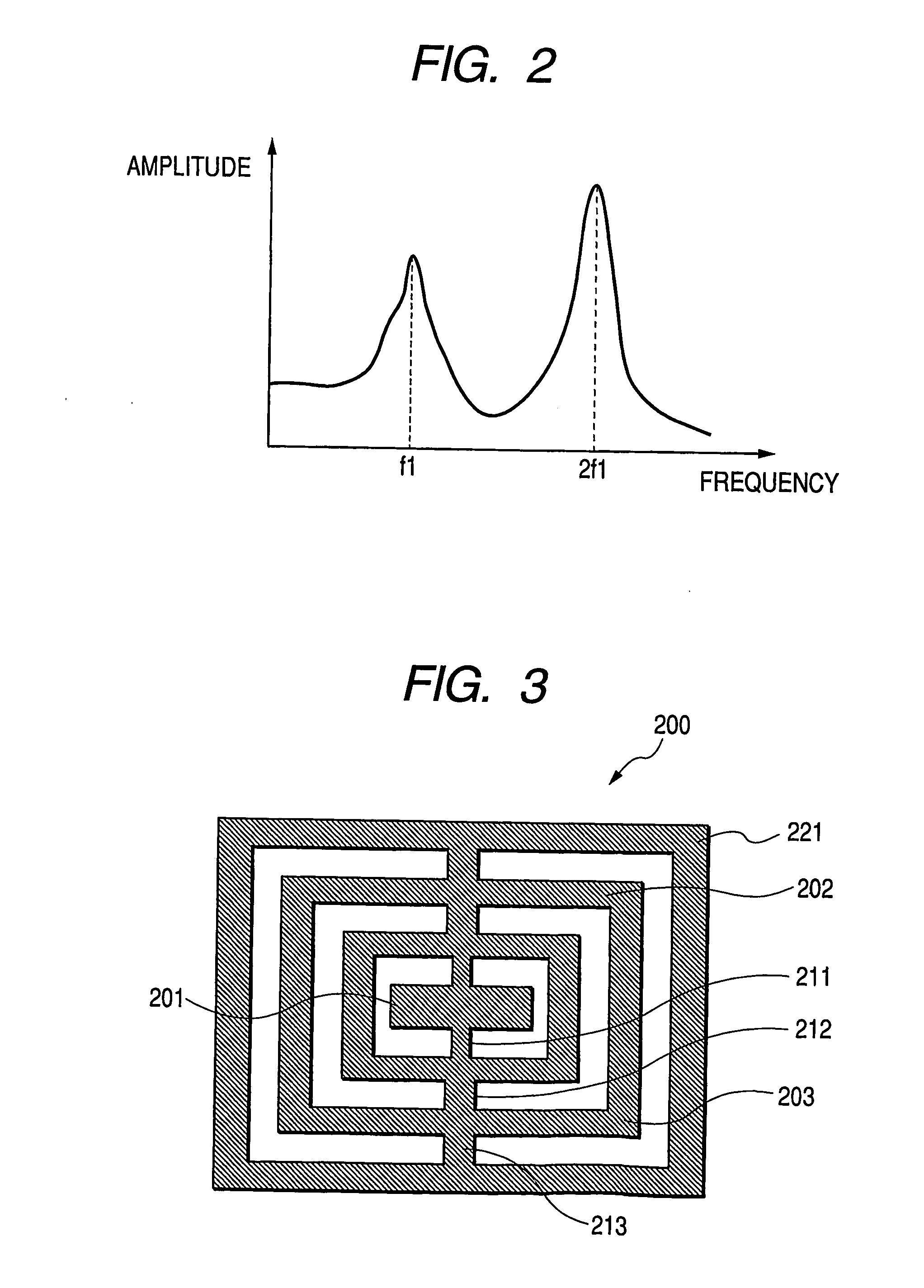
[0080]FIG. 3 is a top view of a plate member 200 formed by etching-working a silicon wafer. Flat movable elements 201 to 203 and torsion springs 211 to 213 are alternately connected in series. The axes of the torsion springs 211 to 213 are linearly arranged, and the other end of the torsion spring 213 is connected to a fixing frame 221. While this system has three oscillation models, the frequencies thereof are adjusted so as to be in relation of approximately 1:2:3. These modes are hereinafter referred to as “model 1”, “mode 2” and “mode 3”.
[0081] As an example, when the moments of inertial of the movable elements 201 to 203 and the torsion spring constants of the torsion springs 211 to 213 are I1, I2, I3, k1, k2, and k3, where I1=2.0E−11 [kgm2], I2=2.0E−10 [kgm2], I3=5.0E−10 [kgm2], k1=6.17854E−3 [Nm / rad], k2=2.03388E−2 [Nm / rad], and k3=3.52534E−2 [Nm / rad], M-1K=(3.08927×10⁸-3.08927×1080-3.08927×1071.32587×108-1.01694×1080-4.06776×1071.11284×108)
is established, and therefore, ...
third embodiment
[0084]FIG. 6 is an example in which the light-deflector of the present invention is applied to the image-forming apparatus such as the laser beam printer. A laser light 311 emitted from a light source 302 is shaped by an emission optical system 303, and is scanned by a light-deflector 301 of the present invention. An image-forming optical system 304 focuses the scanned laser light on a photosensitive drum 305 so as to form a spot. The scanned spot moves along a scanning trajectory 312.
[0085] In the image-forming apparatus of the present embodiment, the drawing of an image is performed in the range of an effective time t1eff shown by 1221 in FIG. 12. As evident from FIG. 11, in the light-deflector of the present invention, a scanning angular velocity fluctuates between θ′min (1212 in FIG. 11) and θ′max (1211 in FIG. 11) during the scanning.
[0086] When an ordinary fθ lens is used for the image-forming optical system 304, the scanning velocity on the photosensitive drum 305 fluctuate...
PUM
 Abstract
Description
Claims
Application Information
 - R&D
- Intellectual Property
- Life Sciences
- Materials
- Tech Scout
- Unparalleled Data Quality
- Higher Quality Content
- 60% Fewer Hallucinations
Browse by: Latest US Patents, China's latest patents, Technical Efficacy Thesaurus, Application Domain, Technology Topic, Popular Technical Reports.
© 2025 PatSnap. All rights reserved.Legal|Privacy policy|Modern Slavery Act Transparency Statement|Sitemap|About US| Contact US: help@patsnap.com


