Servo writer and tape drive system

a technology which is applied in the field of servo writer and tape drive system, can solve the problems of lowering the reliability of magnetic head verification, not going straight ahead, and affecting the accuracy of servo signal writing, so as to reduce the vibration of tape in the tape width direction, the effect of enhancing the guide and allowing the guide to follow the running tap

Inactive Publication Date: 2006-07-13
FUJIFILM HLDG CORP +1
View PDF16 Cites 15 Cited by
  • Summary
  • Abstract
  • Description
  • Claims
  • Application Information

AI Technical Summary

Benefits of technology

[0011] In the above construction, the head guide assembly may, preferably but not necessarily, be provided to restrict the displacement of the tape at positions upstream and downstream of the head.
[0012] In one embodiment, the tape guide arrangement may further include a motor having a drive shaft, wherein the guide is fixed on the drive shaft of the motor, and the drive shaft is supported on the air bearing. In addition, the motor may be adapted to rotate the drive shaft in accordance with movement of the tape wrapped around the guide, which movement is caused by the tape drive system. According to this embodiment, once the motor on which the guide is fixed is activated, the guide can be caused to rotate in accordance with the movement of the running tape, whereby the property of the guide that allows the guide to follow the running tape can be enhanced.
[0013] In another embodiment, the tape guide arrangement may further include a motor having a motor housing and a drive shaft fixed relative to the head, which motor housing is shaped and disposed to serve as the guide, and supported on the air bearing. In addition, the motor may be adapted to rotate the motor housing in accordance with movement of the tape wrapped around the motor housing, which movement is caused by the tape drive system. According to this embodiment, similar to the above embodiment, once the motor of which the motor housing serving as the guide is supported on the air bearing is activated, the motor housing as the guide can be caused to rotate in accordance with the movement of the running tape, whereby the property of the guide that allows the guide to follow the running tape can be enhanced.
[0014] The guide as described above may, preferably but not necessarily, include a first guide disposed upstream of the head unit, and a second guide disposed downstream of the head unit. In this construction, the guide supported with an air bearing is provided both upstream and downstream of the head unit along the tape, and thus the vibration of the tape in the tape width direction can be reduced.
[0015] An angle of wrap with which the tape wraps around the guide may preferably but not necessarily be set at a fixed angle between 45° and 90° inclusive. In this configuration, the distance that the tape wraps around the guide can be so long that the guide supported with the air bearing is allowed to follow the tape more stably, whereby the vibration of the tape in the tape width direction can be reduced more effectively.
[0016] A tape edge guide portion of the head guide assembly and a tape edge guide portion of the guide may preferably but not necessarily be aligned within a tolerance of 100 μm in the tape width direction. In this arrangement, the tape edge guide portion of the guide can be prevented from strongly colliding with the tape edge.

Problems solved by technology

The bearing guides R1-R4 are likely to vibrate due to their looseness in the tape width direction of the magnetic tape MT, which thus causes the magnetic tape MT sliding along a magnetic head 141 of the write head unit 14 to vibrate in the tape width direction, with the result that a servo signal written on the magnetic tape MT would disadvantageously not be neatly aligned with a servo band (i.e., not going straight ahead but meandering).
Also, such vibration of the magnetic tape MT would disadvantageously lower the reliability of verification performed by a magnetic head 152 of the read head unit 15 for the servo signal written on the magnetic tape MT.
Resultantly, the edges of the magnetic tape MT are caused to rub against flanges of the bearing guides R1-R4, which would disadvantageously cause magnetic powder to be scratched off the magnetic tape MT, or otherwise damage the magnetic tape MT and other components.
In addition, the edges of the magnetic tape MT caused to rub against the flanges of the bearing guides R1-R4, would disadvantageously intensify not only the vibration in the tape width direction of the magnetic tape MT sliding along the magnetic head 141 of the write head unit 14, but also the vibration in the tape 15 width direction of the magnetic tape MT sliding along the magnetic head 151 of the read head unit 15, with the former making it more difficult to write the servo signal straight on the servo band without meandering, the latter further lowering the reliability of verification performed by the magnetic head 152 of the read head unit 15 for the servo signal written on the magnetic tape MT.

Method used


Image

  • Servo writer and tape drive system
  • Servo writer and tape drive system
  • Servo writer and tape drive system

Examples


Embodiment Construction

[0031] A detailed description of exemplary embodiments of the present invention will now be given with reference to the drawings.

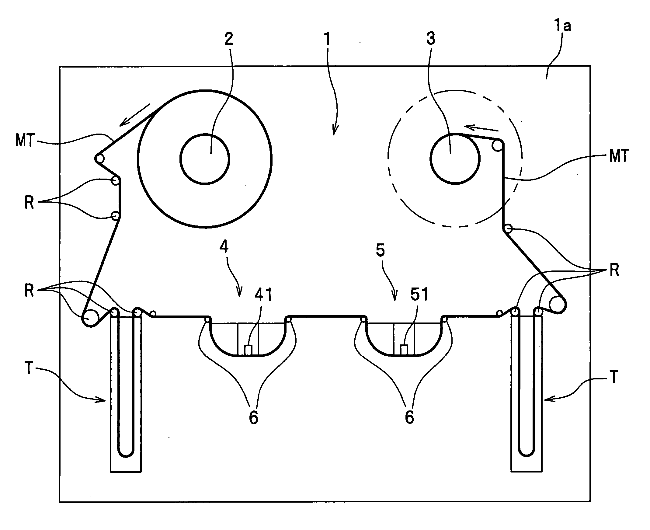
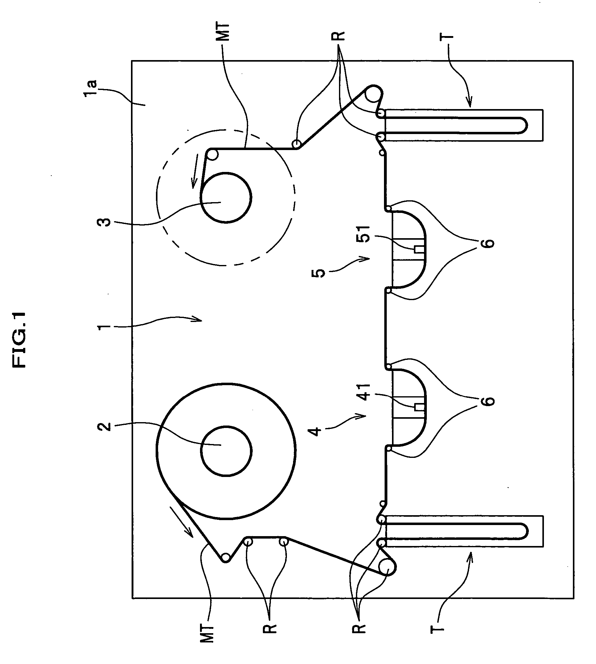
[0032] Referring now to FIG. 1, a servo writer 1 according to one exemplary embodiment of the present invention is provided principally with a supply reel 2, a take-up reel 3, a write head unit 4, and a read head unit 5. Other components further provided in the servo writer 1 include a tensioner T for adjusting a tension of a magnetic tape MT to a predetermined level, guide rollers R for guiding the magnetic tape MT, air bearing guides 6, a power supply (not shown), a drive unit (not shown) for the take-up reel 3, and a cleaning unit for cleaning the magnetic tape MT.

[0033] To manufacture the magnetic tape MT, a wide web roll of magnetic-coated base film is slit into tapes of a product width at the outset. The resulting magnetic tape MT is then wound up into a large-diameter pancake which in turn is set in the supply reel 2 prior to a time when writing o...


PUM

PropertyMeasurementUnit
fixed angleaaaaaaaaaa
widthaaaaaaaaaa

Abstract

A head unit includes a head, and a head guide assembly disposed adjacent to the head to restrict a displacement of a tape (tape-like storage medium) in a tape width direction with respect to the head. A tape drive system includes a tape guide arrangement disposed to guide the tape supplied from a supply reel to the head unit, passed across the head unit and led to a take-up reel. The tape guide arrangement includes a guide disposed adjacent to the head unit, and the guide is supported with an air bearing. In one embodiment, the guide includes a motor for rotating a contact surface of the guide around which the tape is wrapped, in accordance with movement of the tape.

Description

CROSS-REFERENCE TO RELATED APPLIATIONS [0001] This application claims the foreign priority benefit under Title 35, United States Code, § 119 (a)-(d), of Japanese Patent Application No. 2005-005515, filed on Jan. 12, 2005 in the Japan Patent Office, the disclosure of which is herein incorporated by reference in its entirety. BACKGROUND OF THE INVENTION [0002] This invention relates to a servo writer for writing a servo signal on a recordable tape or a tape-like storage medium, which servo signal is used for tracking control exercised over read / write heads, and to a tape drive system for driving a tape-like storage medium. [0003] The rapid-paced advance of information recording / reading and storage medium technologies have been making storage media denser in recent years, and high-density packing has been realized optically or magnetically; for example, 400 gigabytes of data can be stored for computer backup on a reel of magnetic tape. For such high-density packing on a tape-like stora...

Claims


Application Information

Patent Timeline
Patent Type & Authority Applications(United States)
IPC IPC(8): G11B15/00
CPCG11B15/28G11B15/607
Inventor TSUTSUI, KEIICHI
Owner FUJIFILM HLDG CORP
Why Eureka
Try Eureka