

Receiver, transceiver, receiving method and transceiving method
a technology which is applied in the field of receiving method and receiving buffer, can solve the problems of lowering the efficiency of the receive buffer and the inability to transmit data, and achieve the effect of improving the efficiency of the use of the receive buffer and improving the efficiency of data transmission
- Summary
- Abstract
- Description
- Claims
- Application Information
AI Technical Summary
Benefits of technology
Problems solved by technology
Method used
Image

Examples
first embodiment
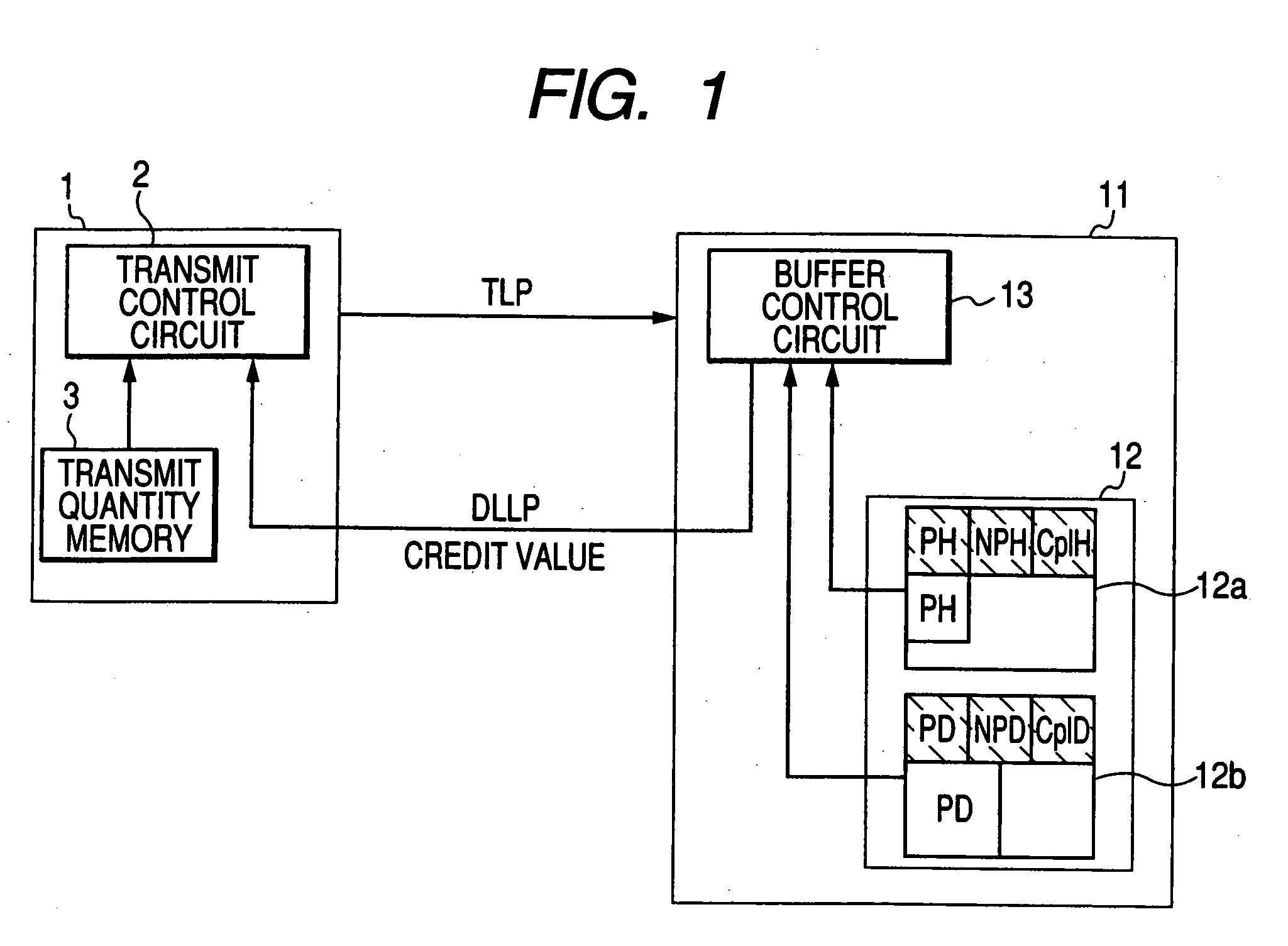
[0027] Embodiments of the invention will be described below in detail with reference to the drawings. FIG. 1 is a block diagram showing a transceiver according to the invention. Although this embodiment is applied to PCI Express Standard, the invention can be applied to various systems for performing flow control on the transmit side in accordance with the vacant capacity of the receive buffer on the receive side.
[0028] For example, a transmitter 1 and a receiver 11 satisfy PCI Express Standard. The transmitter 1 is equivalent to a root complex in PCI Express Standard while the receiver 11 is equivalent to an end point in PCI Express Standard.
[0029] Incidentally, FIG. 1 shows only a configuration concerned with flow control for the transmitter 1 and the receiver 11. Illustration and description about a configuration for achieving other functions will be omitted here.
[0030] In architecture of PCI Express, there is provided a hierarchical structure composed of a transaction layer, a...
second embodiment
[0069] This embodiment is different from the second embodiment in that a receiver 31 having a buffer control circuit 33 instead of the buffer control circuit 23 is used in this embodiment.
[0070] In PCI Express Standard, it is possible to transmit TLPs having no influence on components (hereinafter referred to as “dummy TLPs”). The transmitter 1 can transmit such dummy TLPs to the receiver 31. The receiver 31 does not store the received dummy TLPs in the receive buffer 12 though the receiver 31 receives the dummy TLP.
[0071] That is, the buffer control circuit 33 of the receiver 31 does not increase the credit value of a corresponding data type even in the case where the region of the receive buffer 12 in which the dummy TLPs should be stored is actually opened. That is, in the transmitter 1 transmitting the dummy TLPs, the quantity of transmittable data with respect to the same data type as that of the dummy TLPs is reduced by the capacity of the dummy TLPs.
[0072] In this embodimen...
third embodiment
[0096] Incidentally, the ordinary process for increasing the allocated capacity of the receive buffer 12 on the basis of traffic statistics and the process of reducing the allocated capacity of the receive buffer 12 are the same as those in the
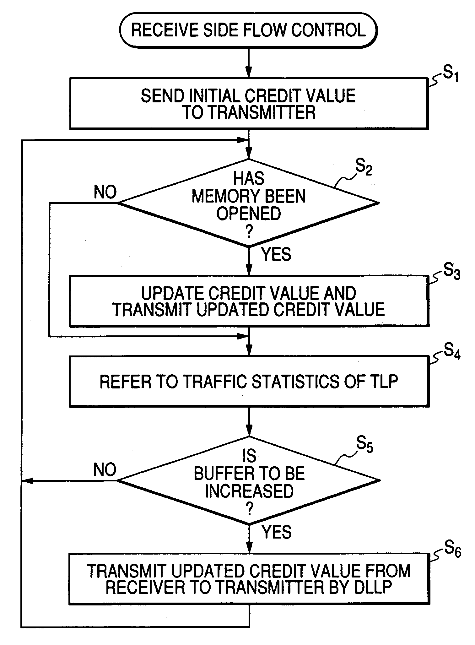
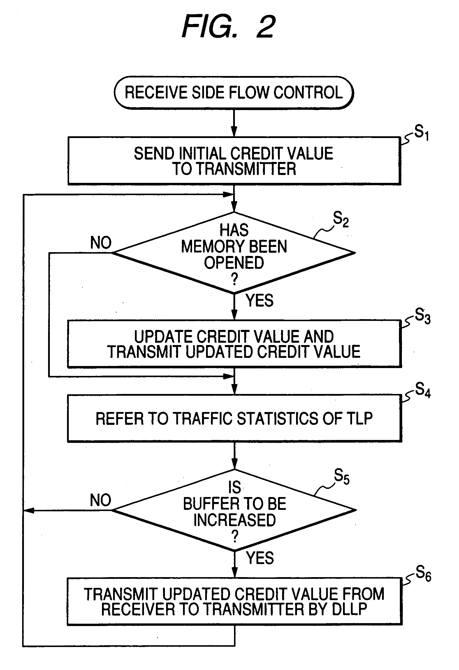
[0097] Next, the operation of the embodiment configured as described above will be described with reference to FIG. 12 which is a flow chart. In FIG. 12, the same steps as shown in FIG. 7 are denoted by the same reference symbols for the sake of omission of duplicated description.
[0098] Assume now that the transmitter 41 cannot transmit TLPs of Completion type data because of shortage of credit. In this case, the process goes from step S30 to step S31 in FIG. 12, so that the transmit control circuit 42 of the transmitter 41 transmits Vendor Specific DLLP to the receiver 51 to make a request to reserve the receive buffer.
[0099] The buffer control circuit 52 of the receiver 51 preferentially increases the allocated capacity of the region CplD ...
PUM
 Abstract
Description
Claims
Application Information