Composite masonry block

a masonry block and composite technology, applied in the field of masonry blocks, can solve the problems of reducing the size of the tongue, compromising the structural integrity, and affecting the appearance of the block tongue or lip

Inactive Publication Date: 2006-07-13
ANCHOR WALL SYST INC
View PDF12 Cites 5 Cited by
  • Summary
  • Abstract
  • Description
  • Claims
  • Application Information

AI Technical Summary

Problems solved by technology

However, when reliance on natural mechanisms is not possible or practical man often resorts to the use of artificial mechanisms such as retaining walls.
However, smaller blocks have to be made with smaller tongues or flanges in order to avoid compromising the structural integrity of the wall with excessive setback.
Manufacturing smaller blocks having smaller tongues using conventional techniques results in a block tongue or lip having inadequate structural integrity.
Concurrently, reducing the size of the tongue or flange with prior processes may weaken and compromise this element of the block, the course, or even the entire wall.
These processes relied on the even flow of a highly viscous and abrasive fill throughout the mold, while also not allowing for under-filling of the mold, air pockets in the fill or the mold, or any other inaccuracies which often occur in block processing.
Any features formed on the block were substantially weaker due to the lack of uniform pressure applied to all elements of the block during formation.
In turn, weaker exterior features on the outside of the block such as an interlocking flange could compromise the entire utility of the block if they crumble or otherwise deteriorate due to improper formation.
The current design of pinless, mortarless masonry blocks generally also fails to resolve other problems such as the ability to construct walls which follow the natural contour of the landscape in a radial or serpentine pattern.
Previous blocks also have failed to provide a system allowing the use of anchoring mechanisms which may be affixed to the blocks without complex pinning or strapping fixtures.
Besides being complex, these pin systems often rely on only one strand or section of a support tether which, if broken, may completely compromise the structural integrity of the wall.
Reliance on such complex fixtures often discourages the use of retaining wall systems by the every day homeowner.
Commercial landscapers generally avoid complex retaining wall systems as the time and expense involved in constructing these systems is not supportable given the price at which landscaping services are sold.

Method used


Image

  • Composite masonry block
  • Composite masonry block
  • Composite masonry block

Examples


Embodiment Construction

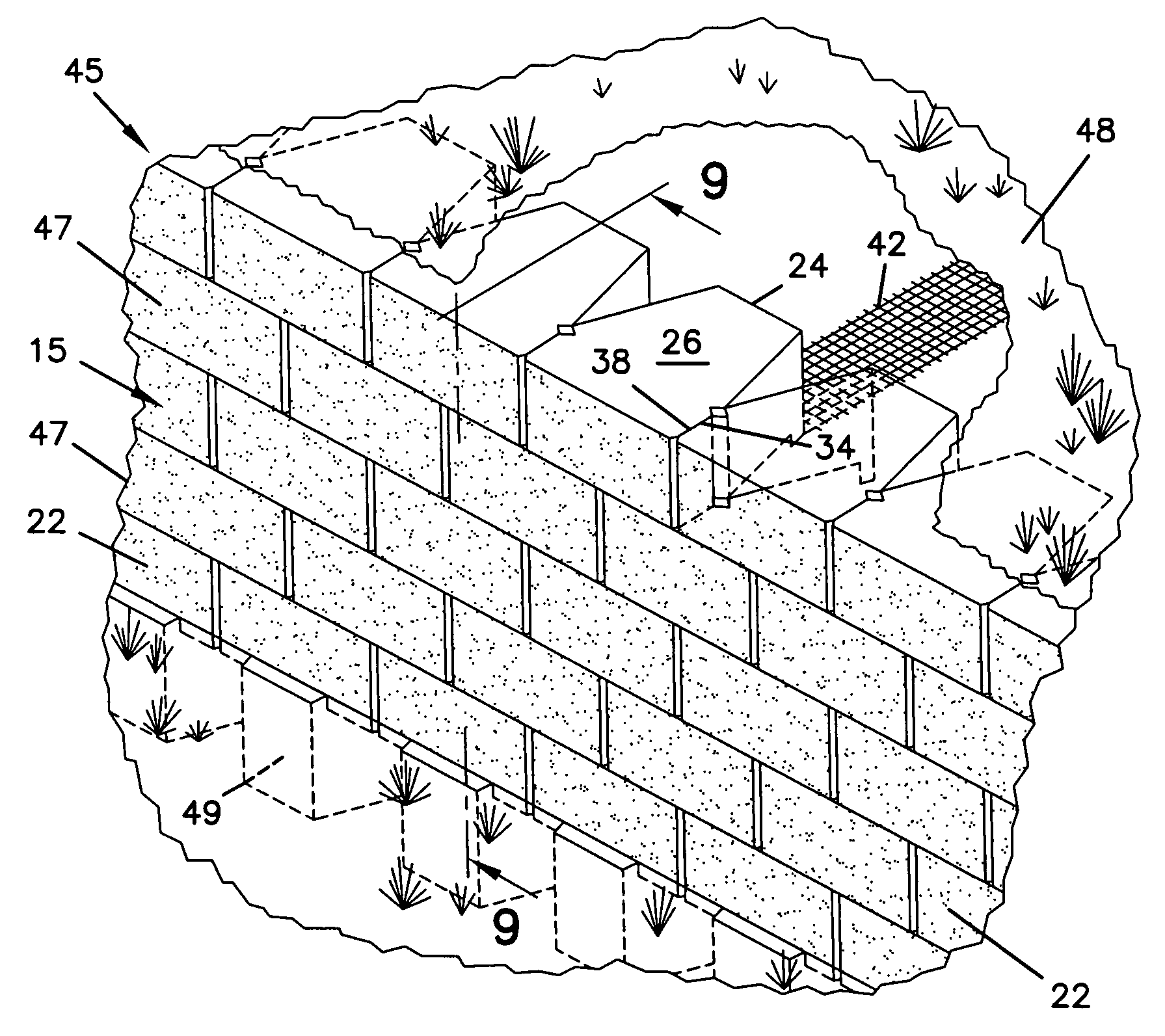
[0028] Accordingly, the present invention provides a composite masonry block, structures resulting from this block, a masonry block mold for use in manufacturing the block of the present invention, and a method of using this mold. The present invention provides a mortarless interlocking masonry block having a high structural integrity which may be used to construct any number of structures having a variety of patterns. Moreover, the block of the present invention is made through a process and mold which facilitates and enhances the formation of a high strength block with an interlocking element which also has a high structural integrity and allows the fabrication of various landscaping structures of high strength.

Composite Masonry Block

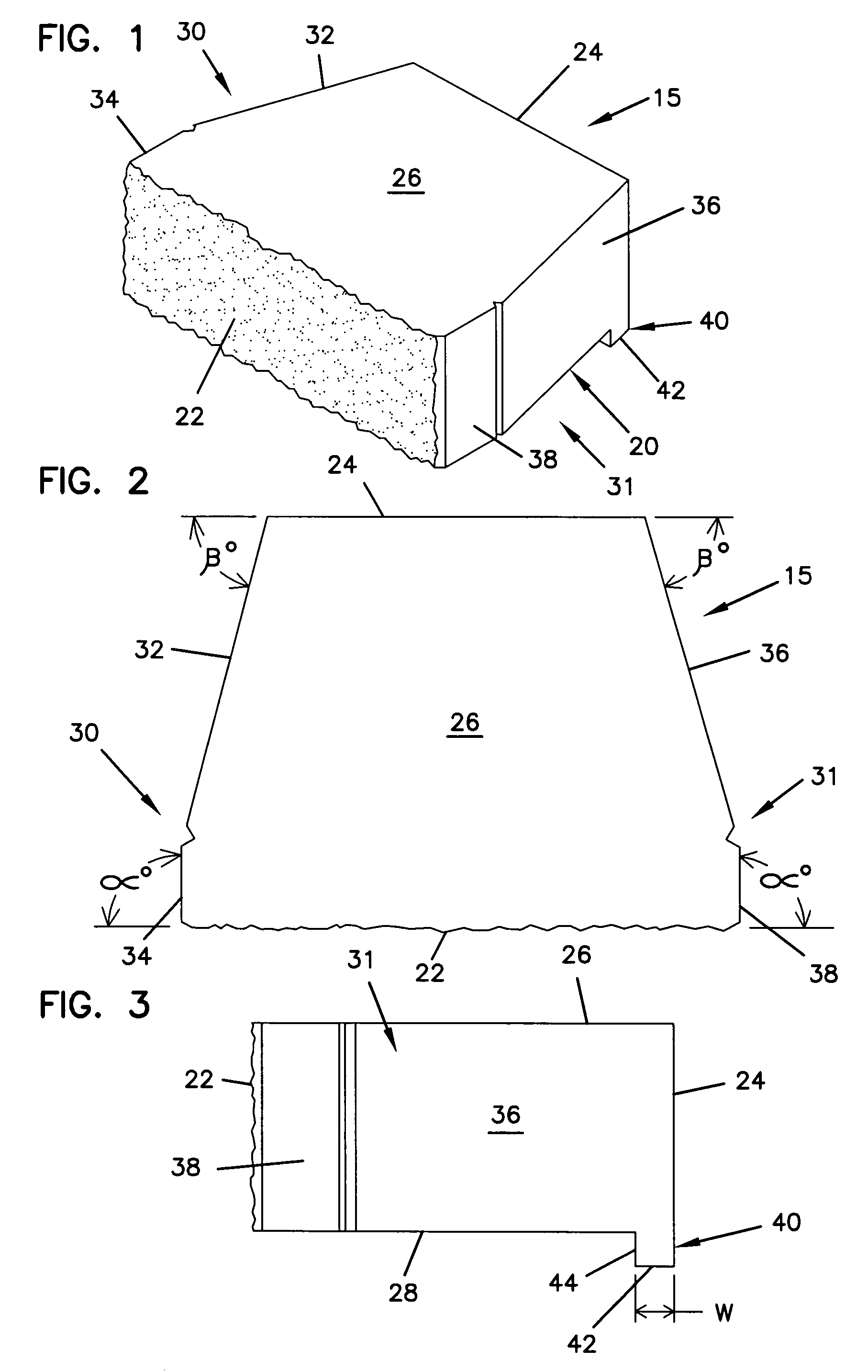
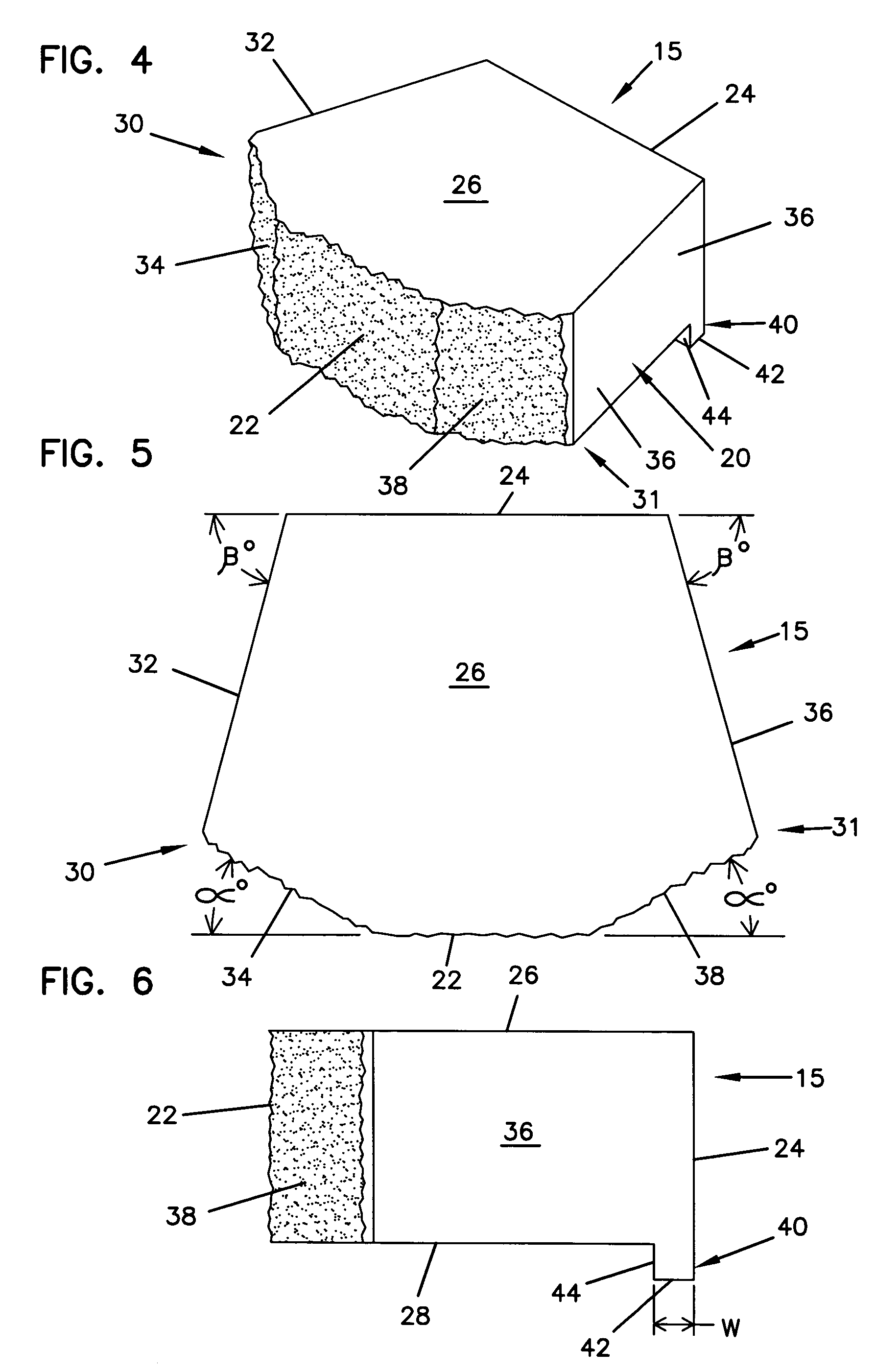
[0029] Referring to the drawings wherein like numerals represent like parts throughout several views, a composite masonry block 15 is generally shown in FIGS. 1-3 and 4-6. The first aspect of the present invention is a composite masonry block having...


PUM

PropertyMeasurementUnit
widthaaaaaaaaaa
angleaaaaaaaaaa
angleaaaaaaaaaa

Abstract

The present invention includes block molds and manufacturing processes as well as a composite masonry block comprising a block body having an irregular trapezoidal shape and comprising a front surface and a back surface, an upper surface and a lower surface, and first and second sidewalls. Both the first and second sidewalls have a first and second part, the sidewall first part extends from the block front surface towards the block back surface at an angle of no greater than ninety degrees in relationship to the block front surface, the sidewall second part surfaces adjoins and lies between the sidewall first parts and the block back surface. The block also has a flange extending from the block back surface past the height of the block. Also disclosed are landscaping structures such as a retaining wall comprising a plurality of the composite masonry blocks of the present invention.

Description

[0001] This patent application is a Continuation-In-Part of U.S. patent application Ser. Nos. 07 / 413,400 and 07 / 413,050 both filed Sep. 28, 1989.FIELD OF THE INVENTION [0002] This invention relates generally to masonry blocks which may be used in the construction of landscaping elements. More specifically, the present invention relates to masonry block manufacturing processes and the resulting high strength masonry blocks which may be used to construct structures such as retaining walls of variable patterns. BACKGROUND OF THE INVENTION [0003] Soil retention, protection of natural and artificial structures, and increased land use are only a few reasons which motivate the use of landscape structures. For example, soil is often preserved on a hillside by maintaining the foliage across that plane. Root systems from trees, shrubs, grass, and other naturally occurring plant life work to hold the soil in place against the forces of wind and water. However, when reliance on natural mechanis...

Claims


Application Information

Patent Timeline
Patent Type & Authority Applications(United States)
IPC IPC(8): E02D5/00E02D17/00B28B7/00B28B7/16B28B17/00E04B2/02E04C1/39
CPCB28B7/0097B28B7/162B28B17/0027B65D2581/3421B65D2581/3494E04B2002/026E04C1/395
Inventor WOOLFORD, MICHAEL E.SIEVERT, DICK J.
Owner ANCHOR WALL SYST INC
Why Eureka
Try Eureka