

Mounting mat for mounting monolith in a polution control device
a technology for mounting mats and monoliths, applied in separation processes, machines/engines, transportation and packaging, etc., can solve problems such as damage, vibration or shock damage, damage, etc., and achieve good or excellent holding pressure
- Summary
- Abstract
- Description
- Claims
- Application Information
AI Technical Summary
Benefits of technology
Problems solved by technology
Method used
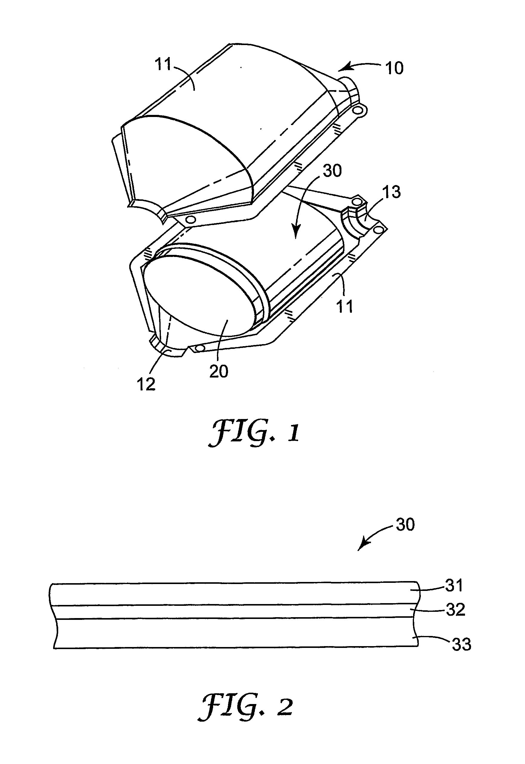
Image

Examples
example 1
[0073] The mounting mat of Example 1 was constructed by using two layers of Maftec™, polycrystalline, MLS-3 needle-bonded blanket, surface density of 800 g / m2 available from Mitsubishi Chemical company (72% Al2O3, 28% SiO2 without binder, bulk density 0.16 g / cm3). A first polycrystalline mat was first sprayed on one major surface with aerosol spray adhesive (available as Foam Adhesive 74 from 3M Company, St. Paul, Minn. / USA). The adhesive-coated surface was then sprinkled with unexpanded vermiculite flakes (available from Cometals, New York, N.Y. / USA). The excess vermiculite was then tipped off.
[0074] The vermiculite-coated surface was then sprayed again with the adhesive and the second layer of polycrystalline mat applied. The construction was then lightly rolled with a rolling pin. The result was a sandwich construction consisting of a layer of vermiculite flakes between two layers of polycrystalline sheet material. The mat construction is summarized in Table 1.
[0075] The mounti...
example 2
[0077] The mounting mat of Example 2 was constructed by using one layer of Maftec™ polycrystalline, MLS-3 needle-bonded blanket, surface density of 800 g / m2, and one layer of 3M INPE 571.02, magnesium aluminium silicate glass mat, surface density of 800 g / m2. The 3M INPE 571.02 mat was sprayed on one side with 3M 74 spray adhesive and then sprinkled with unexpanded vermiculite flakes on the adhesive-coated surface and the excess vermiculite tipped off as in Example 1.
[0078] The vermiculite-coated surface was then sprayed again and the layer of polycrystalline mat applied. The construction was then lightly rolled with a rolling pin. The result was a sandwich construction consisting of a layer of vermiculite flakes between one layers of polycrystalline ceramic sheet material and one layer of magnesium aluminium silicate material. The mat construction is summarized in Table 1.
[0079] The mounting mat of Example 2 was subjected to the Real Condition Fixture Test (RCFT) described above ...
example 3
[0080] The mounting mat of Example 3 was constructed by using a layer of Maftec™, polycrystalline MLS-3, needle-bonded blanket, surface density of 800 g / m2 and a layer of 3M 900 HT, annealed alumino-silicate, ceramic fiber mat, surface density of 1435 g / m2. The polycrystalline mat was sprayed on one side with 3M 74, spray adhesive and then sprinkled with unexpanded vermiculite flakes on the adhesive-coated surface and the excess vermiculite tipped off.
[0081] The vermiculite-coated surface was then sprayed again and the layer of 3M 900 HT mat applied. The construction was then lightly rolled with a rolling pin. The result was a sandwich construction consisting of a layer of vermiculite flakes between one layer of polycrystalline ceramic sheet material and one layer of annealed, alumino-silicate material. The mat construction is summarized in Table 1.
[0082] The mounting mat of Example 3 was subjected to the Real Condition Fixture Test (RCFT) described above under Test Methods. Resul...
PUM
| Property | Measurement | Unit |
|---|---|---|
| uncompressed thickness | aaaaa | aaaaa |
| uncompressed thickness | aaaaa | aaaaa |
| compressed thickness | aaaaa | aaaaa |
Abstract
Description
Claims
Application Information