
Protein microarray device having internal calibrators and methods of using therefor

a technology of microarrays and calibrators, which is applied in the field of protein microarray devices having an internal calibrator, can solve the problems of reducing the number of sample volumes, reducing and reducing the difficulty of generating and validating high density protein arrays for clinical use, etc., and achieves the effects of reducing sample volumes, high variability, and increasing the power of parallel processing

Inactive Publication Date: 2006-07-13
HARVEY MICHAEL A +3
View PDF4 Cites 8 Cited by
  • Summary
  • Abstract
  • Description
  • Claims
  • Application Information

AI Technical Summary

Benefits of technology

[0003] In preferred embodiments, each pad has an immunoglobulin calibrator that is of the same species as the antibody proteins that are reactive to the protein arraying spots. An advantage of the present invention is that one can use reliably use microporous surfaces for conducting quantitative multiplexed protein microimmunoassays with an assurance as to minimal surface-to-surface fluorescence variability on a microarray device.
[0004] (2) Description of the Related Art, Including Information Disclosed Under 37 CFR 1.97 & 1.98
[0005] DNA and protein microarrays have become important methods to allow the simultaneous interrogation of multiple binding reactions (cf. Schena, M. et al., Science 270:467-469(1995), Duggan, D. J., et al., Nature Genetics 21:10-14, (1999), MacBeath, G. and Schrieber, S. L. Science 289:1760-1763(2000). Testing multiple samples at the same time for binding activity against all the elements of a given array significantly increases the power of parallel processing with minimal sample volumes.
[0006] Protein (antigen) microarrays have been recognized as being useful for vaccine development and the serodiagnosis of infectious diseases. (See Bacarese-Hamilton T et alia, Biotechniques 33:S24-S29 (December 2002).) Arrays with controls and calibrators have been shown on glass slides, but the art has recognized that “the development, of protein arrays for research and clinical applications has lagged behind, because of the poor stability of proteins, complex coupling chemistries, high variability, and weak detection signals. High density protein arrays remain difficult to generate and validate for clinical use”. (See Bacarese et alia at S26). REFERENCE TO BENEFIT OF A RELATED PROVISIONAL APPLICATION
[0007] The present invention is entitled to and requests the benefit of the filing date of provisional application Ser. No. 60 / 642,358, filed Jan. 8, 2005. This provisional application bears the same title as above and has been filed in the name of the same inventors. BRIEF SUMMARY OF THE INVENTION
[0008] Methods and devices to provide and improve high throughput analysis of biomolecules (nucleic acids, proteins etc.) are important for elucidation of protein function, diagnostic testing, drug discovery, and drug target identification. One set of technologies that have improved the simultaneous interrogation of large numbers of biomolecules is the use of microarrays. Microarrays are ordered displays of molecules generally immobilized on a surface. Such an array permits the simultaneous investigation of binding of many elements to target molecules. A variety of technologies have been developed to allow investigators to make, process and detect reactions on microarrays.

Problems solved by technology

Arrays with controls and calibrators have been shown on glass slides, but the art has recognized that “the development, of protein arrays for research and clinical applications has lagged behind, because of the poor stability of proteins, complex coupling chemistries, high variability, and weak detection signals.
High density protein arrays remain difficult to generate and validate for clinical use”.

Method used


Image

  • Protein microarray device having internal calibrators and methods of using therefor
  • Protein microarray device having internal calibrators and methods of using therefor
  • Protein microarray device having internal calibrators and methods of using therefor

Examples


Embodiment Construction

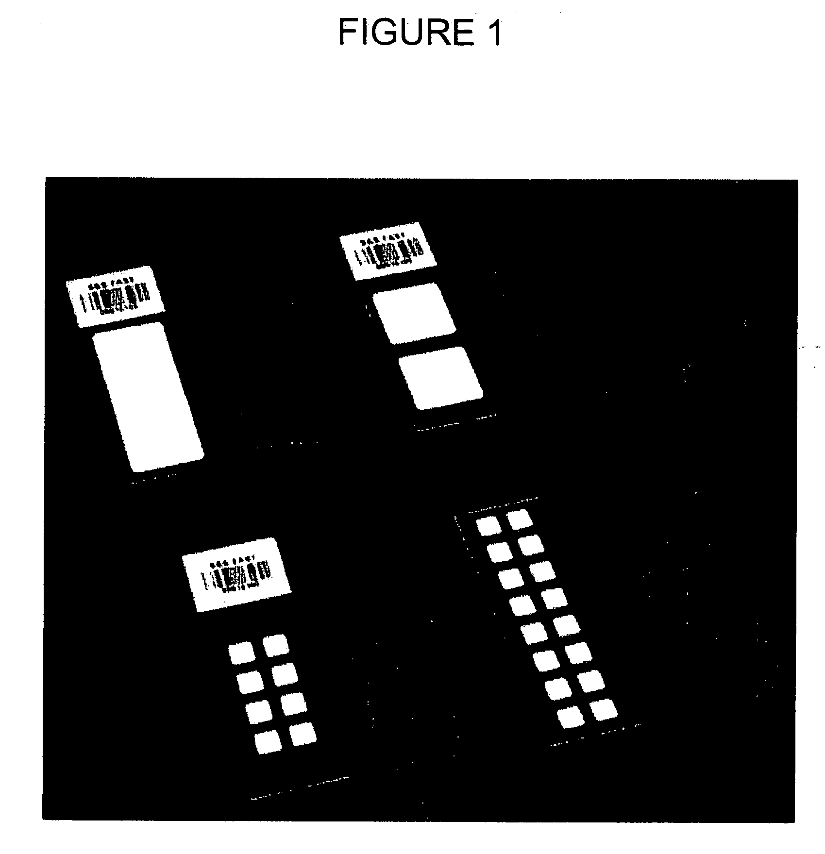
[0029] In preferred embodiments, the present invention relates to a device for preparing multiple assay samples. A preferred embodiment is shown in FIG. 1. The device comprises a standard-sized glass microscope slide (75 mm by 125 mm), comprising a planar support having a set of exterior edges and a planar surface covered with sixteen separate and discretely spaced pads. Each pad has a number of protein arraying spots deposited thereon in distinct patterns. The pads are present at a density and spacing that is registerable with that of a standard 96 well microplate or other conventional microplate formats such as 24 wells, 64 wells, and 384 wells. The device can comprise a series (4) of slides held in a holder sized to the dimensions of an SBS standard multiwell microplate, in this illustration a 96 well microplate having a 9 mm spacing format.

[0030] The pads can be constructed of a protein binding material that is disposed on the support slide. Suitable materials include microporo...


PUM

PropertyMeasurementUnit
thickaaaaaaaaaa
thickaaaaaaaaaa
diameteraaaaaaaaaa

Abstract

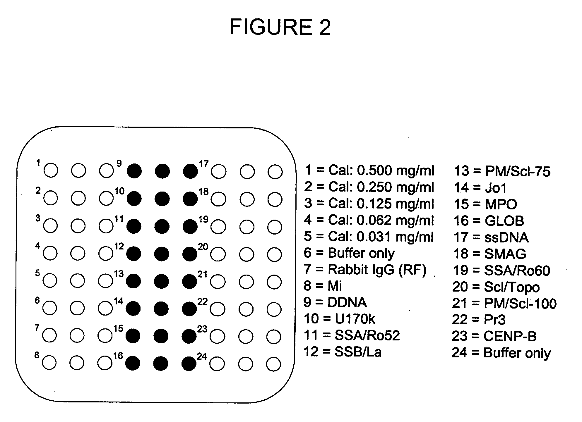
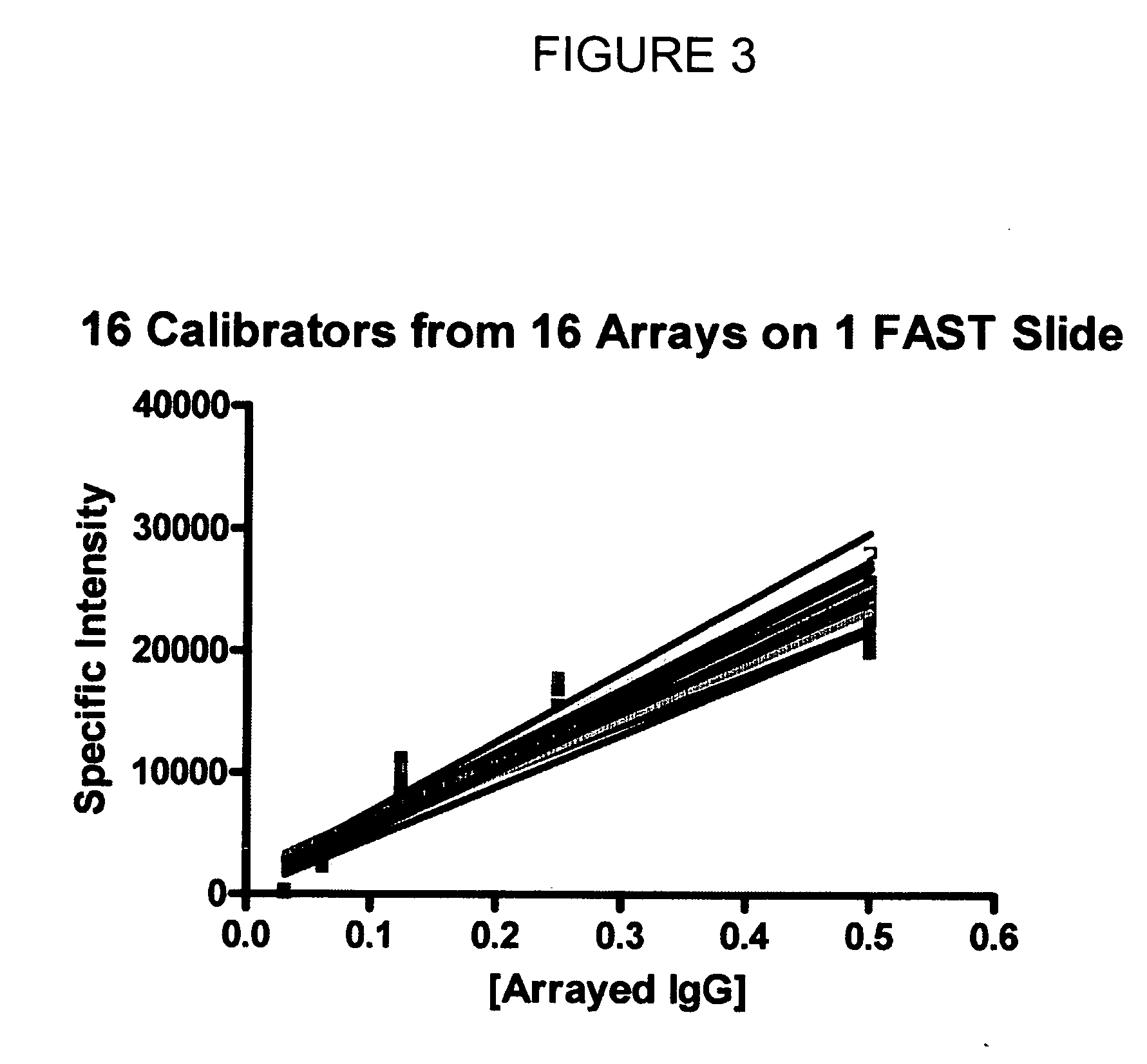
The present invention relates to protein microarray devices having an internal calibrator, kits containing such devices, and methods of using such devices. Such a device comprises a plurality of protein arraying pads on a support substrate, a plurality of protein arraying spots on each pad, and a calibrator disposed on each pad, each calibrator comprising a series of spots of increasing concentration of a protein. In preferred embodiments, each pad has an immunoglobulin calibrator that is of the same species as the proteins that are reactive to the protein arraying spots. An advantage of the present invention is that one can use reliably use microporous surfaces for conducting multiplexed protein microimmunoassays with an assurance as to surface-to-surface fluorescence variability on a microarray device.

Description

BACKGROUND OF THE INVENTION [0001] (1) Field of the Invention [0002] The present invention relates to protein microarray devices having an internal calibrator, kits containing such devices, and methods of using such devices. Such a device comprises a plurality of protein arraying pads on a support substrate, a plurality of protein arraying spots on each pad, and a calibrator disposed on each pad, each calibrator comprising a series of spots of increasing concentration of a protein. [0003] In preferred embodiments, each pad has an immunoglobulin calibrator that is of the same species as the antibody proteins that are reactive to the protein arraying spots. An advantage of the present invention is that one can use reliably use microporous surfaces for conducting quantitative multiplexed protein microimmunoassays with an assurance as to minimal surface-to-surface fluorescence variability on a microarray device. [0004] (2) Description of the Related Art, Including Information Disclosed ...

Claims


Application Information

Patent Timeline
Patent Type & Authority Applications(United States)
IPC IPC(8): G01N33/53C12M1/34
CPCG01N33/54366G01N33/54393
Inventor HARVEY, MICHAEL A.STILLMAN, BRETT A.OWEN, THOMAS P.JUDICE, STEPHEN A.
Owner HARVEY MICHAEL A
Learn More